Mazda 3 Service Manual: DSC HU/CM Inspection
1. Disconnect the DSC HU/CM connector..
2. Connect the negative battery cable..
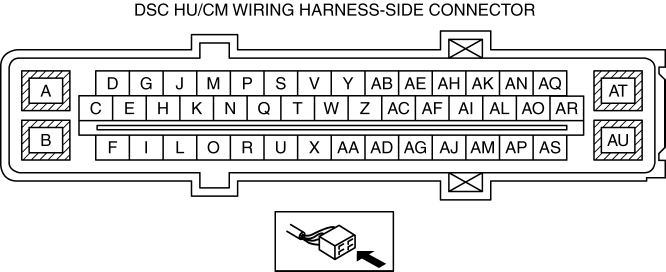
3. Attach the tester lead to the DSC HU/CM wiring harness-side connector and inspect voltage, continuity, or resistance according to the standard (reference) on the table.
Standard (Reference)
|
Terminal |
Signal name |
Connected to |
Measured item |
Measured terminal (measurement condition) |
Standard |
Inspection item(s) |
|
A |
— |
— |
— |
— |
— |
— |
|
B |
Ground |
Ground point |
Continuity |
B—ground point |
Continuity detected |
|
|
C |
— |
— |
— |
— |
— |
— |
|
D |
— |
— |
— |
— |
— |
— |
|
E |
— |
— |
— |
— |
— |
— |
|
F |
LF wheel-speed sensor (-) |
LF wheel-speed sensor |
Continuity |
F—LF ABS wheel-speed sensor terminal B |
Continuity detected |
|
|
G |
— |
— |
— |
— |
— |
— |
|
H |
— |
— |
— |
— |
— |
— |
|
I |
LF wheel-speed sensor (+) |
LF ABS wheel-speed sensor |
Continuity |
I—LF ABS wheel-speed sensor terminal A |
Continuity detected |
|
|
J |
CAN_L |
DLC-2 (CAN_L) |
This terminal is used for communication and cannot be used for malfunction determination during terminal voltage inspection. Perform a DTC inspection. |
|||
|
K |
— |
— |
— |
— |
— |
— |
|
L |
— |
— |
— |
— |
— |
— |
|
M |
CAN_H |
DLC-2 (CAN_H) |
This terminal is used for communication and cannot be used for malfunction determination during terminal voltage inspection. Perform a DTC inspection. |
|||
|
N |
— |
— |
— |
— |
— |
— |
|
O |
RR wheel-speed (+) |
RR ABS wheel-speed sensor |
Continuity |
O—RR ABS wheel-speed sensor terminal A |
Continuity detected |
|
|
P |
— |
— |
— |
— |
— |
— |
|
Q |
— |
— |
— |
— |
— |
— |
|
R |
RR wheel-speed (-) |
RR ABS wheel-speed sensor |
Continuity |
R—RR ABS wheel-speed sensor terminal B |
Continuity detected |
|
|
S |
— |
— |
— |
— |
— |
— |
|
T |
— |
— |
— |
— |
— |
— |
|
U |
— |
— |
— |
— |
— |
— |
|
V |
— |
— |
— |
— |
— |
— |
|
W |
— |
— |
— |
— |
— |
— |
|
X |
— |
— |
— |
— |
— |
— |
|
Y |
Power supply (system) |
Ignition switch or IG1 relay |
Voltage |
Switch the ignition to ON. |
B+ |
|
|
Switch the ignition to off. |
1 V or less |
|||||
|
Z |
— |
— |
— |
— |
— |
— |
|
AA |
— |
— |
— |
— |
— |
— |
|
AB |
— |
— |
— |
— |
— |
— |
|
AC |
— |
— |
— |
— |
— |
— |
|
AD |
— |
— |
— |
— |
— |
— |
|
AE |
— |
— |
— |
— |
— |
— |
|
AF |
— |
— |
— |
— |
— |
— |
|
AG |
LR wheel-speed (-) |
LR wheel-speed sensor |
Continuity |
AG—LR ABS wheel-speed sensor terminal B |
Continuity detected |
|
|
AH |
— |
— |
— |
— |
— |
— |
|
AI |
— |
— |
— |
— |
— |
— |
|
AJ |
LR wheel-speed (+) |
LR ABS wheel-speed sensor |
Continuity |
AJ—LR ABS wheel-speed sensor terminal A |
Continuity detected |
|
|
AK |
DSC OFF switch |
DSC OFF switch |
Continuity |
AK—DSC OFF switch terminal B |
Continuity detected |
|
|
AL |
CAN2_L |
SAS control module |
This terminal is used for communication and cannot be used for malfunction determination during terminal voltage inspection. Perform a DTC inspection. |
|||
|
AM |
— |
— |
— |
— |
— |
— |
|
AN |
— |
— |
— |
— |
— |
— |
|
AO |
CAN2_H |
SAS control module |
This terminal is used for communication and cannot be used for malfunction determination during terminal voltage inspection. Perform a DTC inspection. |
|||
|
AP |
RF wheel-speed (+) |
RF ABS wheel-speed sensor |
Continuity |
AP—RF ABS wheel-speed sensor terminal A |
Continuity detected |
|
|
AQ |
— |
— |
— |
— |
— |
— |
|
AR |
— |
— |
— |
— |
— |
— |
|
AS |
RF wheel-speed (-) |
RF ABS wheel-speed sensor |
Continuity |
AS—RF ABS wheel-speed sensor terminal B |
Continuity detected |
|
|
AT |
Power supply (ABS motor operation) |
Battery |
Voltage |
Under any condition |
B+ |
|
|
AU |
Power supply (solenoid operation) |
Battery |
Voltage |
Under any condition |
B+ |
|

 DSC HU/CM Removal/Installation
WARNING:
If the DSC HU/CM configuration is not completed, it could result in an unexpected
accident due to the DSC being inoperative. If the DSC HU/CM is replaced, always
use the automat ...
Other materials:
Vacuum Line Inspection
MZR 2.0, MZR 2.5, MZR 2.3 DISI Turbo
1. Remove the vacuum hose..
2. Verify that air can be blown from the power brake unit side of the vacuum
hose towards the intake manifold side, and that air cannot be blown in the opposite
direction.
If there is any malfunction of the inner che ...
Front Oil Seal Replacement [Mzr 2.0, Mzr 2.5]
1. Remove the battery cover..
2. Disconnect the negative battery cable..
3. Remove the plug hole plate..
4. Disconnect the wiring harness.
5. Remove the ignition coils..
6. Remove the spark plugs..
7. Remove the ventilation hose.
8. Remove the oil level gauge.
9. Remove the cylinder ...
Filament Repair
1. Clean the filament using isopropyl alcohol.
2. Attach tape to both sides of the filament.
3. Using a small brush or marking pen, apply silver paint.
4. After 2—3 min, carefully remove the tape without damaging the applied
area.
CAUTION:
Do not operate the rear window defrost ...
