Mazda 3 Service Manual: Rear ABS Wheel Speed Sensor Inspection
Installation Visual Inspection
1. Inspect for the following:
-
If there is any malfunction, replace the part.
a. Excessive looseness or play of the rear ABS wheel-speed sensor
b. Deformation of the rear ABS wheel-speed sensor
c. Deformation or damage of the rear ABS sensor rotor
Clearance Inspection
1. Remove the rear ABS wheel-speed sensor.
2. Measure the distance between the rear ABS wheel-speed sensor installation surface and the rear ABS sensor rotor. This is dimension A.
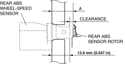
3. Calculate the clearance between the rear ABS wheel-speed sensor and the rear ABS sensor rotor using the following formula:
-
Clearance (mm {in}) = A –13.9 {0.547}
4. Verify that the clearance between the rear ABS sensor rotor and the rear ABS wheel-speed sensor is as indicated below.
-
If there is any malfunction, replace it.
-
Clearance
-
1.46 mm {0.057 in} or less
Sensor Output Value Inspection
CAUTION:
-
Resistance inspection using other testers may cause damage to the ABS wheel-speed sensor internal circuit. Be sure to use the M-MDS to inspect the ABS wheel-speed sensor.
1. Switch the ignition to off.
2. Connect the M-MDS to the DLC-2.

3. Select the following PIDs using the M-MDS:
-
WSPD_LR
(LR wheel-speed sensor)
-
WSPD_RR
(RR wheel-speed sensor)
4. Start the engine and drive the vehicle.
5. Verify that the display of the M-MDS shows the same value as the speedometer.
-
If there is any malfunction, replace the rear ABS wheel-speed sensor.
 Precaution [ABS]
1. Any one or a combination of the ABS warning and brake system warning lights
illuminates even when the system is normal.
Warning lights that may illuminate and/or flash
...
 Rear ABS Wheel Speed Sensor Removal/Installation
1. Remove the under cover..
2. Remove in the order indicated in the table.
3. Install in the reverse order of removal.
1
Connector
2
Bolt
...
Other materials:
Air Bleeding
CAUTION:
If the strainer is removed, impurities may penetrate the power steering system
and damage it. To prevent this, always bleed air with the strainer installed.
Do not maintain the steering wheel fully turned for 5 s or more. The oil
temperature could rise and damage ...
Manual Transaxle Removal/Installation [A26 M R]
CAUTION:
Secure the steering wheel using tape or a cable to prevent the steering shaft
from rotating after disconnecting the steering shaft. If the steering wheel
rotates after the steering shaft and the steering gear and linkage are disconnected,
the internal parts of the clock spr ...
Up Switch Inspection [Fw6 A EL]
Continuity Inspection
NOTE:
The up switch is built into the selector lever component.
1. Remove the battery cover..
2. Disconnect the negative battery cable..
3. Remove the console..
4. Disconnect the selector lever component connector.
5. Verify that the continuity betwee ...
