Mazda 3 Service Manual: Steering Gear And Linkage Inspection
Steering Rack Inspection
1. Inspect for cracking, damage, and tooth wear.
-
If there is any malfunction, replace the steering rack.
2. Measure the steering rack warp.
-
If it exceeds the maximum specification, replace the steering rack.
-
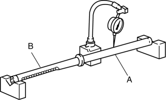
Steering rack runout
-
Large diameter portion (near point A): 0.15 mm {0.006 in} max.
-
Small diameter portion (near point B): 0.20 mm {0.008 in} max.
Tie-rod End Inspection
1. Inspect the tie-rod end for damage and the boot for cracks.
-
If there is any malfunction, replace the tie-rod end.
2. Inspect for excessive play.
-
If there is any malfunction, replace the tie-rod end.
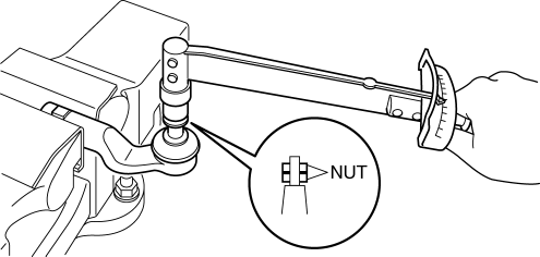
3. Rotate the ball joint 5 times
.
4. Install two nuts to the ball joint and measure the tie-rod end rotational torque using a torque wrench.
-
If not within the specification, replace the tie-rod end.
-
Tie-rod end rotational torque
-
0.5—3.0 N·m {5.1—30 kgf·cm, 4.5—26 in·lbf}
Tie rod Inspection
1. Inspect for bending and damage.
-
If there is any malfunction, replace the tie rod.
2. Inspect for excessive play.
-
If there is any malfunction, replace the tie rod.
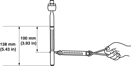
3. Swing the ball joint 10 times
.
4. Measure the ball joint swing torque using a pull scale.
-
If it exceeds the specification, replace the tie rod.
-
Tie rod swing torque
-
0.4—4.0 N·m {4.1—40 kgf·cm, 3.6—35 in·lbf}
-
[Pull scale reading 0.6—29.3 N {0.06—2.98 kgf, 0.14—6.58 lbf}]
 Steering Gear And Linkage Disassembly
CAUTION:
To prevent damage to the steering gear, secure it to the vise using a copper
plate or clean cloth.
1. Disassemble in the order indicated in the table.
1
...
 Steering Gear And Linkage Removal/Installation
CAUTION:
Performing the following procedures without first removing the ABS wheel-speed
sensor may possibly cause an open circuit in the wiring harness if it is pulled
by mistake. Before ...
Other materials:
Message Indicated on Display*
If a message is displayed in the center display (type B audio), take
appropriate action (in a
calm manner) according to the displayed message.
Stop Vehicle in Safe Place Immediately
If the following messages are displayed in the center display (type B audio),
a vehicle
system may be malf ...
Battery Recharging [Mzr 2.3 Disi Turbo]
Using GR8-1291:
(See GR8-1291 INSTANT TRAINING MODULE (VIDEO) .)
WARNING:
Keep all flames away from the battery, otherwise evaporated gas from the
battery fluid may catch fire and cause serious injury.
1. Remove the battery filler caps and check the water level. If necessary, add ...
Automatic Transaxle Shift Mechanism Removal/Installation
Selector Lever Removal/Installation
1. Remove the battery cover..
2. Disconnect the negative battery cable..
3. Remove in the order indicated in the table.
4. Install in the reverse order of removal.
1
Upper panel
(See UPPER PANEL REMOVAL/INSTALLATION.)
...
