Mazda 3 Service Manual: Engine Tune Up [Mzr 2.0, Mzr 2.5]
NOTE:
-
If the accelerator pedal is depressed continuously for a specified time, the engine speed may decrease to the idle speed. This is due to the fuel cut control operation, which prevents overheating, and it does not indicate a malfunction.
Engine Tune-up Preparation
1. Verify the following:
-
MTX: Shift lever is in neutral position.
-
ATX: Selector lever is in P or N position.
2. Warm up the engine to normal operating temperature.
a. Increase the engine speed to 2,500—3,000 rpm
until the cooling fan starts running.
b. When the cooling fan starts running, release the accelerator pedal and wait until the cooling fan stops running.
3. Turn off all electrical loads.
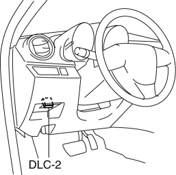
4. Connect the M-MDS to the DLC-2.
Idle Speed Inspection
NOTE:
-
Idle speed is not adjustable.
-
Idle speed verification requires M-MDS.
1. Complete the engine tune-up preparation..
2. Verify that the idle speed (M-MDS: RPM) is within the specification..
-
Idle speed (MTX: Neutral position, ATX: P, N position)
-
600—700 rpm (MTX), 650—750 (ATX)
Ignition Timing Inspection
NOTE:
-
The ignition timing cannot be adjusted.
-
The M-MDS is required to verify the ignition timing.
1. Complete the engine tune-up preparation..
2. Verify the ignition timing (M-MDS: SPARKADV) using the PID/data monitor function of the M-MDS..
-
Ignition timing
-
MZR 2.0: Approx. BTDC 8°
-
MZR 2.5: Approx. BTDC 12°
3. Verify that ignition timing advances when the engine speed increases gradually.
Idle Mixture Inspection
1. Verify that the idle speed and ignition timing are within the specification..
2. Insert an exhaust gas analyzer into the tailpipe.
3. Verify that the CO and HC concentrations are within regulation.
-
CO concentration
-
Within the regulation
-
HC concentration
-
Within the regulation
Idle-up Speed Control Inspection
NOTE:
-
Idle speed is not adjustable.
-
Idle speed verification requires M-MDS.
1. Complete the engine tune-up preparation..
2. Verify that the engine speed (M-MDS: RPM) is within the specification when each load is applied. (The speed decrease just after the load is applied is not considered.).
-
If the engine speed is not within the specification when a specified load is applied, inspect the related input parts, wiring harnesses, and connectors.
-
Idle-up speed (MTX: Neutral position, ATX: P, N position)
-
A/C on: 700—800 rpm (MTX), 650—770 (ATX)
-
Electrical loads on: 650—800 rpm
 Engine SST [Skyactiv G 2.0]
1: Mazda SST number
2: Global SST number
Example
1:49 UN20 5072
2:205–072
Holder
1: –
2: 134-01049A
Evaporative emission system t ...
 Engine Tune Up [Mzr 2.3 Disi Turbo]
NOTE:
If the accelerator pedal is depressed continuously for a specified time,
the engine speed may decrease to the idle speed. This is due to the fuel cut
control operation, which preve ...
Other materials:
Torque Converter Clutch (TCC) Non Operation [Fw6 A EL]
TROUBLESHOOTING ITEM
Torque converter clutch (TCC) non-operation
DESCRIPTION
TCC does not operate when vehicle reaches TCC operation range.
POSSIBLE CAUSE
Signal malfunction
...
Customization
Customizable features
The Subaru Solterra is equipped with a wide range of configurable
electronic systems that allow you to tailor vehicle behavior and comfort settings
according to your personal preferences. These adjustments can be performed via the
multi-information display, the multimedi ...
Transaxle Range (TR) Switch Removal/Installation [FS5 A EL]
CAUTION:
Water or foreign objects entering the connector can cause a poor connection
or corrosion. Be sure not to drop water or foreign objects on the connector
when disconnecting it.
1. Engage the parking brake and use wheel chocks at the front and rear of the
wheels.
2. Shi ...
