
Mazda 3 Service Manual: Liftgate Latch Switch Inspection
1. Disconnect the negative battery cable..
2. Remove the following parts:
a. Liftgate upper trim.
b. Liftgate side trim.
c. Liftgate lower trim.
d. Liftgate latch and lock actuator.
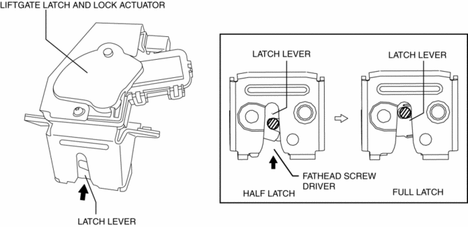
3. Press the latch in using a flathead screwdriver to inspect the latch lever condition.
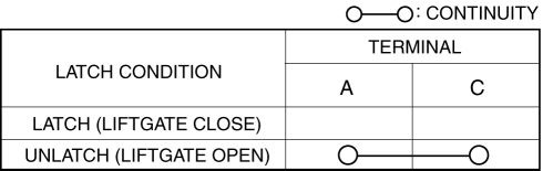
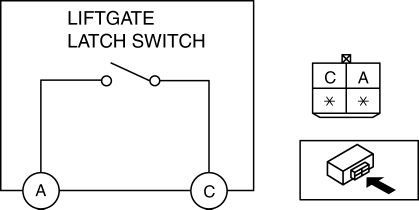
4. Verify that the continuity is as indicated in the table.
-
If not as indicated in the table, replace the liftgate latch and lock actuator
 Liftgate Latch And Lock Actuator Removal/Installation
1. Disconnect the negative battery cable..
2. Remove the following parts:
a. Liftgate upper trim.
b. Liftgate side trim.
c. Liftgate lower trim.
3. Disconnect the connector.
4. Remove ...
 Liftgate Lock Striker Removal/Installation
1. Remove the trunk end trim..
2. Remove the bolts, then remove the liftgate lock striker.
3. Install in the reverse order of removal.
4. Adjust the liftgate lock striker.. ...
Other materials:
Intake Air System Removal/Installation [Mzr 2.0, Mzr 2.5]
WARNING:
A hot engine and intake air system can cause severe burns. Turn off the engine
and wait until they are cool before removing the intake air system.
Fuel is very flammable liquid. If fuel spills or leaks from the pressurized
fuel system, it will cause serious injury or d ...
ABS HU/CM Removal/Installation
WARNING:
If the ABS HU/CM configuration is not completed, it could result in an unexpected
accident due to the ABS being inoperative. If the ABS HU/CM or ABS CM is replaced,
always use the automatic configuration function so that the ABS operation conditions
are correct.
CAUTI ...
Manual Transaxle Shift Mechanism Removal/Installation [G35 M R]
1. Remove the battery cover..
2. Disconnect the negative battery cable.
3. Remove the battery component. (ex: battery, battery tray and PCM component).
4. Remove the air cleaner component..
5. Remove the aerodynamic under cover NO.2..
6. Remove the tunnel member (rear)..
7. Remove the u ...
