Mazda 3 Service Manual: Variable Valve Timing Actuator Inspection [Mzr 2.3 Disi Turbo]
CAUTION:
-
Variable valve timing actuator cannot be disassembled because it is a precision unit.
1. Remove the battery cover..
2. Disconnect the negative battery cable..
3. Remove the charge air cooler..
4. Remove the ignition coils..
5. Disconnect the ventilation hose from the cylinder head cover..
6. Remove the cylinder head cover..
7. Inspect the variable valve timing actuator for damage around the stopper pin cap (A), or a missing stopper pin cap (B), spring and stopper.
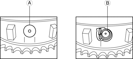
-
If no parts are damaged or missing, go to the next step.
-
If any parts are damaged or missing, replace the variable valve timing actuator..
CAUTION:
-
If any parts are damaged or missing, remove the front cover to inspect the timing and oil pump chains and all related components for damage as a result of lost parts. Replace components if necessary.
-
If the lost parts cannot be located in the timing chain area, it will be necessary to remove the oil pan to retrieve them.
8. Turn the crankshaft clockwise so that the notches on the variable valve timing actuator can be checked.
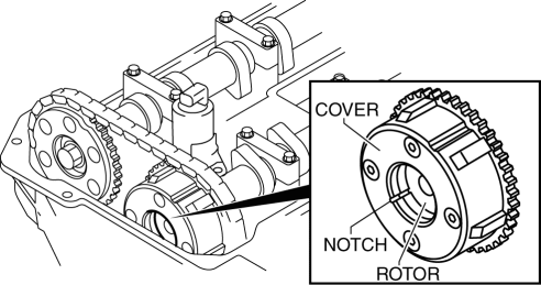
9. Turn the camshaft counterclockwise to align the notches on the variable valve timing actuator.
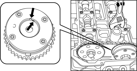
10. With the notches aligned, turn the camshaft clockwise 30 degrees.
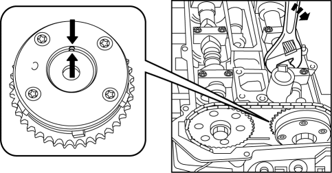
11. Verify the notches again.
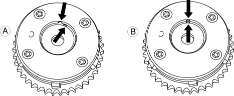
-
A: If the notches are not aligned, replace the variable valve timing actuator..
-
B: If the notches are aligned, there is no problem with the variable valve timing actuator.
NOTE:
-
In some rare cases, the timing chain tensioner ratchet lock may get stuck, which will require the removal of the engine front cover.
12. Install in the reverse order of removal.
 Variable Valve Timing Actuator Inspection [Mzr 2.0, Mzr 2.5]
CAUTION:
Variable valve timing actuator can not be disassembled because it is a precision
unit.
1. Remove the battery cover..
2. Disconnect the negative battery cable..
3. Remove ...
 Variable Valve Timing Actuator Removal/Installation [Mzr 2.0, Mzr 2.5]
NOTE:
Variable valve timing actuator can not be disassembled because it is a
precision unit.
Intake camshaft sprocket is integrated with the variable valve timing actuator
and ca ...
Other materials:
Rear Window Wiper and
Washer
The ignition must be switched ON to use
the wiper.
Rear Window Wiper
Turn the wiper on by turning the rear
wiper/washer switch
Rear Window Washer
To spray washer fluid, turn the rear wiper/
washer switch to the position. After the
switch is released, the washer will stop.
If the w ...
Fuel Filter (High Pressure) Removal/Installation [Mzr 2.0, Mzr 2.5]
WARNING:
Fuel is very flammable liquid. If fuel spills or leaks from the pressurized
fuel system, it will cause serious injury or death and facility breakage. Fuel
can also irritate skin and eyes. To prevent this, always complete the “Fuel
Line Safety Procedure”, while referring to ...
Cruise Control Set Vehicle Speed Display
The vehicle speed preset using the cruise
control is displayed.
Trip Computer and INFO Switch
The following information can be selected
by pressing the up or down
part of the
INFO switch with the ignition switched
ON.
Approximate distance you can travel on
the available fuel
Ave ...
