
Mazda 3 Service Manual: Wheel Hub, Steering Knuckle Removal/Installation
CAUTION:
-
Performing the following procedures without first removing the ABS wheel-speed sensor may possibly cause an open circuit in the wiring harness if it is pulled by mistake. Before performing the following procedures, disconnect the ABS wheel-speed sensor connector (axle side) and fix the wiring harness to an appropriate place where it will not be pulled by mistake while servicing the vehicle.
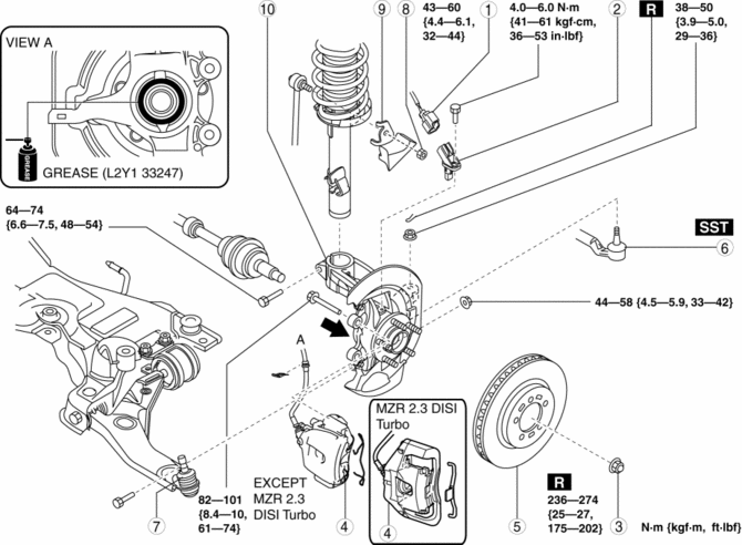
1. Remove in the order indicated in the table.
2. Install in the reverse order of removal.
3. After installation, inspect the front wheel alignment and adjust it if necessary..
|
1 |
ABS wheel-speed sensor connector |
|
2 |
ABS wheel-speed sensor |
|
3 |
Locknut |
|
4 |
Brake caliper component (See Brake Caliper Component Removal Note.) (See FRONT BRAKE (DISC) REMOVAL/INSTALLATION [MZR 2.0, SKYACTIV-G 2.0, MZR 2.5].) (See FRONT BRAKE (DISC) REMOVAL/INSTALLATION [MZR 2.3 DISI Turbo].) |
|
5 |
Disc plate |
|
6 |
Tie-rod end ball joint . |
|
7 |
Front lower arm ball joint (See Front Lower Arm Ball Joint Installation Note.) |
|
8 |
Stabilizer control link upper nut |
|
9 |
Dynamic damper |
|
10 |
Wheel hub, steering knuckle component (See Wheel Hub, Steering Knuckle Component Removal Note.) (See Wheel Hub, Steering Knuckle Component Installation Note.) |
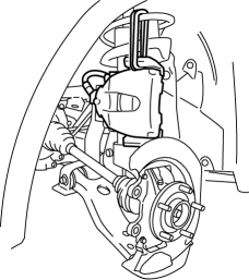
Brake Caliper Component Removal Note
1. Remove the retaining clip, mounting support installing bolt and suspend it out of the way using a cable.
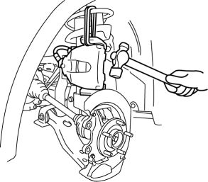
Wheel Hub, Steering Knuckle Component Removal Note
1. Separate the shock absorber from the wheel hub, steering knuckle component by tapping the upper part of the steering knuckle with a hammer.
Wheel Hub, Steering Knuckle Component Installation Note
1. Apply grease (L2Y1 33247) to the wheel bearing inner race and drive shaft contact surface (Area A in figure).
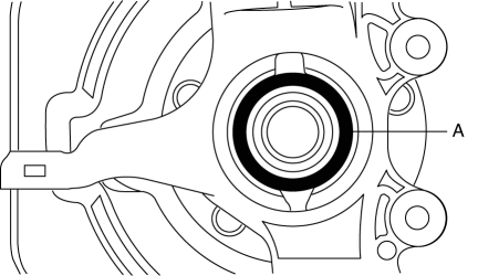
2. Install the wheel hub, steering knuckle component.
Front Lower Arm Ball Joint Installation Note
NOTE:
-
The bolt insertion direction can be either front or rear of the vehicle, however, keep the insertion direction the same on both the left and right sides of the vehicle.
 Wheel Hub, Steering Knuckle Inspection
Wheel Bearing Excessive Play Inspection
1. Install the magnetic base and dial gauge as shown in the figure and measure
the wheel bearing axial excessive play.
If it exceeds the maximum ...
 Rear Suspension
...
Other materials:
Tiedown Hooks
CAUTION
Do not use the front and rear tiedown
eyelets for towing the vehicle.
They have been designed only for
securing the vehicle to a transport
vessel during shipping.
Using the eyelets for any other purpose
could result in the vehicle being
damaged.
Tiedown H ...
Mass Air Flow (MAF) Sensor Inspection [Mzr 2.0, Mzr 2.5]
Visual Inspection
1. Remove the battery cover..
2. Disconnect the negative battery cable..
3. Disconnect the MAF/IAT sensor connector.
4. Remove the MAF/IAT sensor..
5. Visually inspect the MAF/IAT sensor for the following:
Damage, cracks, soiling
Rusted sensor terminal
...
Automatic Transaxle Controls
Various Lockouts:
Indicates that you must depress
the brake pedal and hold in the lock-release
button to shift (The ignition must be switched ON).
Indicates the shift lever can be
shifted freely into any position.
Indicates that you must hold in
the lock-release button to shift.
NO ...
