Mazda 3 Owners Manual: Commander switch operation
NOTE For safety reasons, some operations are disabled while the vehicle is being driven.
Volume dial operation
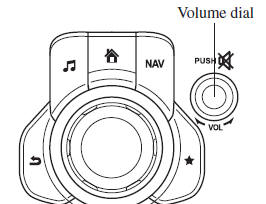
Press the volume dial to switch the audio MUTE on and off.
Turn the volume dial to adjust the volume. The volume increases by turning the dial clockwise, and decreases by turning it counterclockwise.
Switches around commander knob
The following operations can be done by pressing the switches around the commander knob.
 : Displays the home screen.
 : Displays the Entertainment screen.
 : Displays the Navigation screen
(Only navigation-equipped vehicles). For operation
of the Navigation screen, refer to the navigation system manual. If the SD card
for the
navigation system is not inserted, the compass indicating the direction in which
the vehicle
is moving is displayed.
 : Displays the Favorites screen.
Long-press to store particular items in Favorites. (Radio,
phonebook and destination of the navigation system can be programmed.)
 : Returns to previous screen.
Commander knob operation
(Selection of icons on screen)
- Tilt or turn the commander knob and move the cursor to the desired icon.
- Press the commander knob and select the icon.
NOTE Long-press operation of the commander knob is also possible for some functions.
Touch panel operation
| CAUTION Do not press the screen strongly or press it with a sharp-pointed object. Otherwise, the screen could be damaged. |
NOTE For safety reasons, operation of the center display is disabled while the vehicle is being driven. However, items not displayed in gray can be operated using the commander switch while the vehicle is being driven.
 Audio Set (Type B)
NOTE
The explanation of functions described in this manual may differ from the actual
operation, and the shapes of screens and buttons and the letters and characters
displayed
may also differ fro ...
 Basic Operation Method
TOUCH & TAP
Touch or tap on the item indicated on the screen.
The operation is launched and the next item is displayed.
SLIDE
Touch the setting item displaying a slider bar.
Tou ...
Other materials:
Call interrupt
A call can be interrupted to receive an
incoming call from a third party.
Switch to a new incoming call using the
following methods.
Method 1
Press the pick-up button.
Prompt: “Swapping calls.”
Method 2
Press the talk button with a short press.
Say: [Beep] “Swap calls”
...
Heater Core Inspection
1. Inspect the heater core for damage, cracks, and water leakage.
If there is any malfunction, replace the heater core.
2. Visually inspect the fins for bending.
If there is any bending, use the end of a flathead screwdriver to straighten
the fins.
3. Visually inspect ...
Shift Position Indication
The selector position is indicated when the
ignition is switched ON.
Gear position indication
In manual shift mode, the “M” of the shift
position indication illuminates and the
numeral for the selected gear is displayed.
Warning Light
The warning light turns on when the
system has a ma ...
