
Mazda 3 Service Manual: Information Display Removal/Installation
CAUTION:
-
When replacing the information display, the configuration procedure must be performed before removing the information display. The information display will not operate normally if it is replaced without performing the configuration procedure.
1. Perform the information display configuration when replacing it..
2. Disconnect the negative battery cable..
3. Remove the following parts:
a. Upper column cover.
b. Instrument cluster.
c. Center panel.
d. Audio unit.
e. Center cover.
f. Dashboard upper panel.
g. Hole cover.
4. Remove the screws and wiring harness clip.
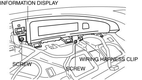
5. Remove the information display.
6. Disconnect the connector.
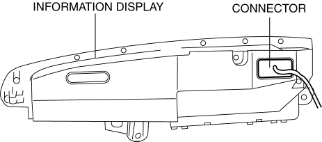
7. Install in the reverse order of removal.
 Information Display Input/Output Check Mode
NOTE:
In this mode, it is possible to verify the items in the following chart.
Check Code Table
Check code
Check item
Related items
...
 Instrument Cluster Configuration
1. Connect the M-MDS (IDS) to the DLC-2.
2. After the vehicle is identified, select the following items from the initialization
screen of the IDS.
Select the “Module Programming”.
...
Other materials:
i-ELOOP
On conventional vehicles, the kinetic energy that is generated when the
vehicle is
decelerated by applying the brakes or during engine braking ends up being
discarded as
heat. By utilizing this discarded kinetic energy to generate electricity and use
it to power the
vehicle's electrical dev ...
Rear Center Speaker Inspection
1. Disconnect the negative battery cable..
2. Remove the following parts:
a. Rear seat cushion.
b. Rear scuff plate.
c. Tire house trim.
d. C-pillar trim.
e. Rear package trim.
f. Rear center speaker.
3. Verify the resistance between the rear center speaker terminals.
If ...
DSC Sensor Initialization Procedure
WARNING:
If the DSC sensor initialization procedure is not completed, the DSC will
not operate properly and it might cause an unexpected accident. Therefore, after
replacing or removing the DSC HU/CM or SAS control module, make sure to perform
the DSC sensor initialization procedure ...
