
Mazda 3 Service Manual: Throttle Position (TP) Sensor Inspection [Mzr 2.0, Mzr 2.5]
Voltage Inspection
CAUTION:
-
The inspection cannot be performed with this method correctly if there is a malfunction of the APP sensor or throttle valve actuator. Verify that no DTCs related to the APP sensor or throttle valve actuator are stored before the inspection.
NOTE:
-
The TP sensor cannot be removed as a single unit. When replacing the TP sensor, replace it together with the throttle body as a single unit.
1. Connect the M-MDS to the DLC–2.
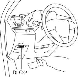
2. Switch the ignition to ON.
3. Verify that the TP sensor output voltage (PID: TP1, TP2) varies according to the accelerator opening angle when the accelerator opening angle is gradually increased..
-
If verified, go to the next step.
-
If not as verified, replace the throttle body..
4. Verify that the TP sensor output voltage (PID: TP1, TP2) is within the specification when the accelerator pedal is depressed and not depressed..
-
If not as specified, replace the throttle body..
 Throttle Body Inspection [Mzr 2.0, Mzr 2.5]
Resistance Inspection
1. Remove the battery cover..
2. Disconnect the negative battery cable..
3. Disconnect the throttle body connector.
4. Measure the resistance between throttle body termina ...
 Variable Tumble Shutter Valve Switch Inspection [Mzr 2.0, Mzr 2.5]
Voltage Inspection
NOTE:
The variable tumble shutter valve switch cannot be removed as a single unit.
When replacing the variable tumble shutter valve switch, replace it together
with t ...
Other materials:
Ventilator Grille Removal/Installation
Side Ventilator grille
1. Through the wiring harness into the position shown in the figure, remove the
side ventilator grille in the direction of arrow.
2. When installing the side ventilator grille, push it for the dashboard.
Center Ventilator grille
1. Disconnect the negative battery c ...
Brake Hose (Rear) Removal/Installation [Mzr 2.0, Skyactiv G 2.0]
CAUTION:
If the brake hose is installed to the caliper on the vehicle, the tool cannot
be installed correctly resulting in brake fluid leakage due to improper installation.
Therefore, remove the caliper and brake hose as a single unit when removing
the brake hose, and tighten the br ...
Ignition Switch Removal/Installation [Without Advanced Keyless Entry And Push
Button Start System]
1. Disconnect the negative battery cable..
2. Remove the column cover..
3. Detach the tab.
4. Pull the pin in the direction of the arrow shown in the figure and release
the lock.
5. Disconnect the ignition switch connector and key interlock solenoid connector.
6. Remove the ...
