Mazda 3 Service Manual: Wheel Hub, Steering Knuckle Disassembly/Assembly
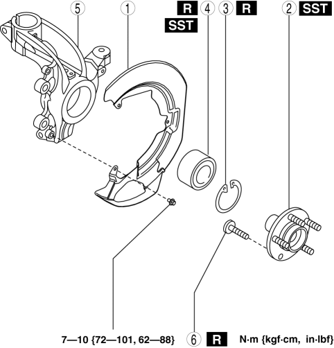
1. Disassemble in the order indicated in the table.
|
1 |
Dust Cover |
|
2 |
Wheel hub component . |
|
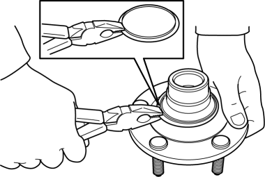
3 |
Retaining clip |
|
4 |
Wheel bearing (See Wheel Bearing Removal Note.) (See Wheel Bearing Installation Note.) |
|
5 |
Steering knuckle |
|
6 |
Hub bolt (See Wheel Hub Bolt Removal Note.) (See Wheel Hub Bolt Installation Note.) |
2. Assemble in the reverse order of disassembly.
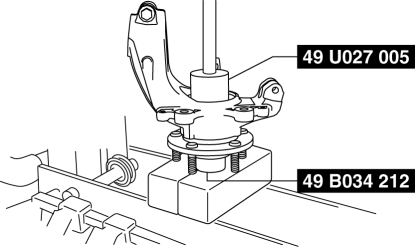
Wheel Hub Component Removal Note
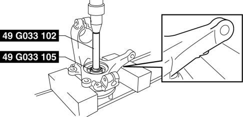
1. Remove the wheel hub component using the SSTs
.
2. If the bearing inner race remains on the front wheel hub component, perform the following procedure:
Without using SST
1. Grind a section of the bearing inner race until approx. 0.5 mm {0.02 in}
remains.
2. Remove the bearing inner race using a chisel.
With using SST
1. Remove the part as shown in the figure.
2. Position the SSTs
and a spare bolt (M10 length 90 mm {3.5 in} or less) as shown in the figure.
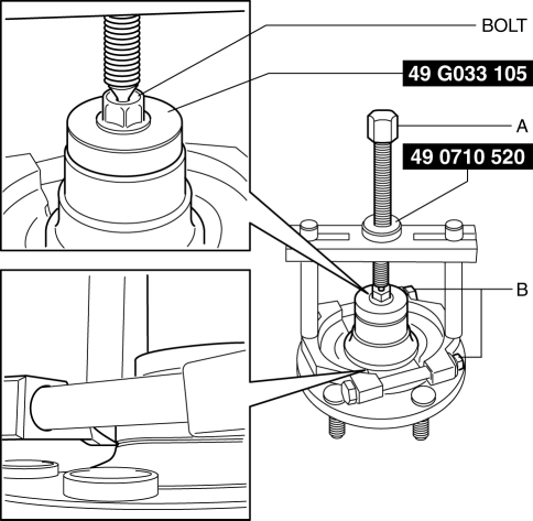
CAUTION:
-
When tightening section A, tighten section B securely because the engagement of the SST tab is shallow and it can come off easily.
3. Tighten SST
section A until the space between the bearing inner race and wheel hub component is 1—2 mm {0.04—0.07 in}
.
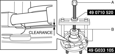
4. Temporarily loosen SST
section A and position the SST
again.
5. Tighten SST
section A and remove the bearing inner race.
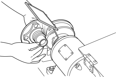
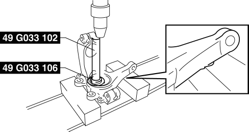
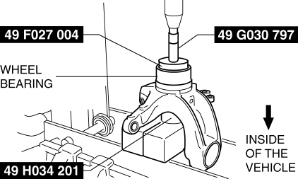
Wheel Bearing Removal Note
1. Remove the wheel bearing using the SSTs
.
Wheel Hub Bolt Removal Note
NOTE:
-
The hub bolts do not need to be removed unless they are being replaced.
1. Remove the hub bolt using a press.
Wheel Hub Bolt Installation Note
1. Install the new hub bolt using a press.

Wheel Bearing Installation Note
NOTE:
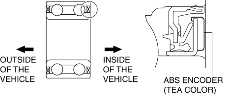
-
Install the wheel bearing with the ABS encoder (tea color) facing inside of the vehicle.
1. Install the new wheel bearing using the SSTs
.
Wheel Hub Component Installation Note
1. Install the wheel hub component using the SSTs
.
 Front Wheel Hub Bolt Replacement
1. Remove the brake calliper component and disc plate..
2. Remove the wheel hub bolt using the SST as shown in the figure.
NOTE:
When removing the wheel hub bolts, perform the work bet ...
 Wheel Hub, Steering Knuckle Inspection
Wheel Bearing Excessive Play Inspection
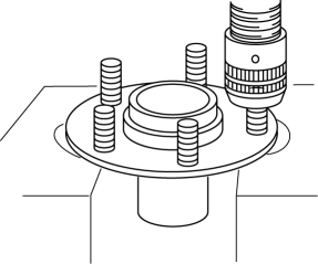
1. Install the magnetic base and dial gauge as shown in the figure and measure
the wheel bearing axial excessive play.
If it exceeds the maximum ...
Other materials:
Relay Block Removal/Installation [With Advanced Keyless Entry And Push Button
Start System]
1. Disconnect the negative battery cable..
2. Remove the following parts:
a. Driver-side front scuff plate.
b. Driver-side front side trim.
c. Hood release lever.
d. Upper panel.
e. Shift knob (MTX)(See MANUAL TRANSAXLE SHIFT MECHANISM REMOVAL/INSTALLATION
[G66M-R].)(See MANUAL TRANSAX ...
Clutch Cover Inspection [C66 M R]
1. Remove the clutch cover..
2. Perform the following procedures to inspect the clutch cover.
If it exceeds the maximum specification, replace the clutch cover..
a. Measure the wear of the diaphragm spring fingers.
Clutch cover diaphragm spring fingers maximum depth
0.6 ...
Vacuum Pump Removal/Installation [Skyactiv G 2.0]
1. Remove the plug hole plate..
2. Remove the battery and battery tray..
3. Pinch open the clamp using pliers and disconnect the vacuum hose from the
vacuum pump.
4. Remove in the order shown in the table.
5. Install in the reverse order of removal.
1
Vacu ...
