Mazda 3 Service Manual: PID/Data Monitor Inspection [Two Step Deployment Control System]
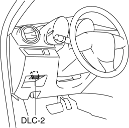
1. Connect the M-MDS (IDS) to the DLC-2.

2. After the vehicle is identified, select the following items from the initialization screen of the IDS.
a. Select “DataLogger”.
b. Select “Modules”.
c. Select “RCM”.
3. Select the applicable PID from the PID table.
4. Verify the PID data according to the directions on the screen.
NOTE:
-
The PID data screen function is used for monitoring the calculated value of input/output signals in the module. Therefore, if the monitored value of the output parts is not within the specification, it is necessary to inspect the monitored value of input parts corresponding to the applicable output part control. In addition, because the system does not display an output part malfunction as an abnormality in the monitored value, it is necessary to inspect the output parts individually.
 PID/Data Monitor Inspection [Standard Deployment Control System]
1. Connect the M-MDS (IDS) to the DLC-2.
2. After the vehicle is identified, select the following items from the initialization
screen of the IDS.
a. Select “DataLogger”.
b. Select “Module ...
 Passenger Side Air Bag Module Removal/Installation [Standard Deployment Control
System]
WARNING:
Handling the air bag module improperly can accidentally deploy the air bag
module, which may seriously injure you. Read the air bag system service warnings
and cautions before h ...
Other materials:
Child-Restraint System Installation
Child-Restraint System Types
In this owner's manual, explanation of
child-restraint systems is provided for the
following three types of popular childrestraint
systems: infant seat, child seat,
booster seat.
NOTE
Installation position is determined
by the type of child-restraint system.
...
Dashboard Illumination
When the position lights are turned
on with the ignition switched ON,
the brightness of the instrument panel
illumination is dimmed.
NOTE
When the position lights are turned on,
the position lights indicator light in the
instrument cluster turns on.
Refer to Headlights on .
The brightness ...
Battery Removal/Installation [Mzr 2.0, Mzr 2.5]
1. Remove in the order indicated in the table.
2. Install in the reverse order of removal.
1
Battery cover
(See Battery Cover Removal Note.)
(See Battery Cover Installation Note.)
2
Negative battery cable
3
...
