Mazda 3 Service Manual: Turbocharger Inspection [Mzr 2.3 Disi Turbo]
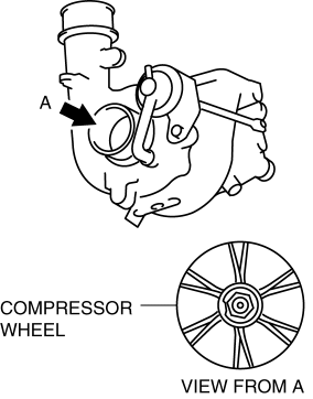
Compressor Wheel Inspection
1. Remove the turbocharger..
2. Visually inspect the compressor wheel from view A for the cracks, damage, or bending on all the compressor wheel blades.
-
If there are any cracks or damage, replace the turbocharger..
NOTE:
-
If there is contact between the compressor wheel and compressor housing, there may be cracks, damage, or bending on the blade end area.
-
If there are cracks, damage, or bending on the compressor wheel, verify the following after replacing the turbocharger.
-
Intake air/exhaust system related components
-
Oil outlet pipe and oil inlet pipe damage
-
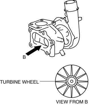
Turbine Wheel Inspection
1. Remove the turbocharger..
2. Visually inspect the turbine wheel from view B for the cracks, damage, or bending on all the turbine wheel blades.
-
If there are cracks, damage, or bending on the turbine wheel, replace the turbocharger..
NOTE:
-
If there is contact between the turbine wheel and turbine housing, there may be cracks, damage, or bending on the blade end area.
-
If there are cracks, damage, or bending on the turbine wheel, verify the following after replacing the turbocharger.
-
Intake air/exhaust system related components
-
Oil outlet pipe and oil inlet pipe damage
-
 Input/Turbine Speed Sensor Removal/Installation [FS5 A EL]
CAUTION:
Always use a new bolt. If the removed input/turbine speed sensor installation
bolt is reused, it may cause oil leakage.
A sealant coating is applied to the input/turbine s ...
 Wastegate Actuator Inspection [Mzr 2.3 Disi Turbo]
1. Remove the air hose and air duct..
2. Disconnect the hose from the wastegate actuator.
3. Plug the wastegate actuator as shown in the figure.
4. Connect the vacuum pump to the port
5. R ...
Other materials:
Rear Combination Light Removal/Installation
4SD
1. Disconnect the negative battery cable..
2. Remove the following parts:
a. Trunk mat.
b. Trunk board.
c. Trunk end trim.
d. Trunk side trim.
3. Disconnect the connectors shown in the figure and remove the nuts.
4. Pull the rear combination light in the direction of the arrow ...
Glass Panel Adjustment
1. Fully close the glass panel.
2. Measure the gap and height between the glass panel and body.
If not as specified, loosen the glass panel installation screws and reposition
the glass panel.
Clearance (4SD)
a: -2.4—0.2 mm {-0.09—0.01 in}
b: 0 mm {0 in}
...
Shift position
Choose the appropriate shift position in your Subaru Solterra according
to your driving needs, road conditions, and intended operation.
Shift position purpose and functions
In the Subaru Solterra, the shift system is designed to deliver smooth, intuitive
control while maximizing safety a ...
