Mazda 3 Service Manual: ABS HU/CM Inspection
1. Disconnect the ABS HU/CM connector..
2. Connect the negative battery cable..
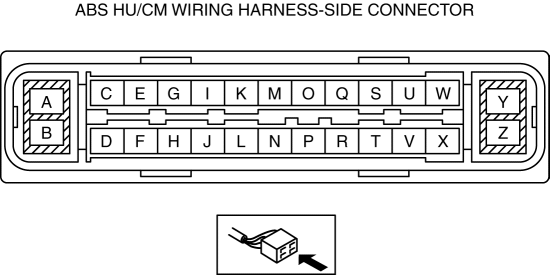
3. Attach the tester lead to the ABS HU/CM wiring harness-side connector and inspect the voltage, continuity, or resistance according to the standard (reference value) in the table below.
Standard (reference)
|
Terminal |
Signal name |
Connected to |
Measured item |
Measured terminal (measurement condition) |
Standard |
Inspection item(s) |
|
A |
− |
− |
− |
− |
− |
− |
|
B |
Ground |
Ground point |
Continuity |
B—ground point |
Continuity detected |
|
|
C |
RR wheel-speed (-) |
RR ABS wheel-speed sensor |
Continuity |
C–RR ABS wheel-speed sensor connector terminal B |
Continuity detected |
|
|
D |
− |
− |
− |
− |
− |
− |
|
E |
RR wheel-speed (+) |
RR ABS wheel-speed sensor |
Continuity |
E–RR ABS wheel-speed sensor connector terminal A |
Continuity detected |
|
|
F |
− |
− |
− |
− |
− |
− |
|
G |
− |
− |
− |
− |
− |
− |
|
H |
CAN_H |
DLC-2 (CAN_H) |
This terminal is used for communication and cannot be used for malfunction determination during terminal voltage inspection.Perform a DTC inspection. |
|||
|
I |
LF wheel-speed (+) |
LF ABS wheel speed sensor |
Continuity |
I–LF ABS wheel-speed sensor connector terminal A |
Continuity detected |
|
|
J |
− |
− |
− |
− |
− |
− |
|
K |
LF wheel-speed (-) |
ABS wheel-speed sensor (LF) |
Continuity |
K–LF ABS wheel-speed sensor connector terminal B |
Continuity detected |
|
|
L |
CAN_L |
DLC-2 (CAN_L) |
This terminal is used for communication and cannot be used for malfunction determination during terminal voltage inspection.Perform a DTC inspection. |
|||
|
M |
− |
− |
− |
− |
− |
− |
|
N |
Power supply (System) |
Ignition switch or IG1 relay |
Voltage |
Switch the ignition to ON |
B+ |
|
|
Switch the ignition to off |
1 V or less |
|||||
|
O |
RF wheel-speed (-) |
RF ABS wheel-speed sensor |
Continuity |
O–RF ABS wheel-speed sensor terminal B |
Continuity detected |
|
|
P |
− |
− |
− |
− |
− |
− |
|
Q |
RF wheel-speed (+) |
RF ABS wheel-speed sensor |
Continuity |
Q–RF ABS wheel-speed sensor terminal A |
Continuity detected |
|
|
R |
− |
− |
− |
− |
− |
− |
|
S |
− |
− |
− |
− |
− |
− |
|
T |
− |
− |
− |
− |
− |
− |
|
U |
LR wheel-speed (+) |
LR ABS wheel-speed sensor |
Continuity |
U–LR ABS wheel-speed sensor connector terminal A |
Continuity detected |
|
|
V |
− |
− |
− |
− |
− |
− |
|
W |
LR wheel-speed (-) |
LR ABS wheel-speed sensor |
Continuity |
W–LR ABS wheel-speed sensor connector terminal B |
Continuity detected |
|
|
X |
− |
− |
− |
− |
− |
− |
|
Y |
Power supply (Solenoid operation, ABS motor operation) |
Battery |
Voltage |
Under any condition |
B+ |
|
|
Z |
− |
− |
− |
− |
− |
− |
 ABS
ABS
...
 ABS HU/CM Removal/Installation
WARNING:
If the ABS HU/CM configuration is not completed, it could result in an unexpected
accident due to the ABS being inoperative. If the ABS HU/CM or ABS CM is replaced,
always use t ...
Other materials:
Water Pump Removal/Installation [Mzr 2.0, Mzr 2.5]
WARNING:
Never remove the cooling system cap or loosen the radiator drain plug while
the engine is running, or when the engine and radiator are hot. Scalding engine
coolant and steam may shoot out and cause serious injury. It may also damage
the engine and cooling system.
Tu ...
Driving Tips
WARNING
Do not let the vehicle move in a
direction opposite to the direction
selected by the selector lever:
Do not let the vehicle move backward
with the selector lever in a forward
position, or do not let the vehicle
move forward with the selector lever
in the revers ...
Schedule 2
Chart symbols:
I: Inspect: Inspect and clean, repair, adjust, fill up, or replace if
necessary.
R: Replace
L : Lubricate
C: Clean
T: Tighten
Remarks:
*1 Use of FL-22 is recommended when replacing engine coolant. Using engine
coolant other than FL-22 may
cause serious damage to the en ...
