Mazda 3 Service Manual: Antenna Feeder No.3 Removal/Installation
4SD (With Audio Unit (With Display))
1. Disconnect the negative battery cable..
2. Remove the rain sensor cover. (Vehicles with auto light/wiper system).
3. Disconnect the rain sensor connector. (Vehicles with auto light/wiper system)
4. Partially peel back the seaming welts.
5. Remove the following parts:
a. Sunroof seaming welt (vehicles with sunroof)
b. A-pillar trim.
c. Front scuff plate.
d. Rear scuff plate.
e. B-pillar lower trim.
f. Upper anchor of the front seat belt.
g. B-pillar upper trim.
h. Rear seat cushion.
i. Tire house trim.
j. C-pillar trim.
k. Map light.
l. Sunvisor.
m. Assist handle.
n. Headliner.
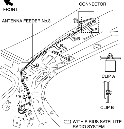
6. Disconnect the antenna feeder No.5.
7. Remove the clips A and B.
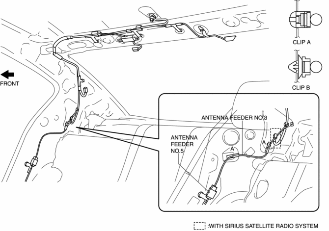
8. Disconnect the antenna amplifier connector.
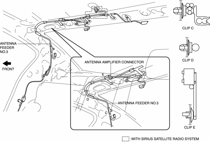
9. Remove the clips C, D and E
10. Disconnect the center roof antenna connector. (with SIRIUS satellite radio system)
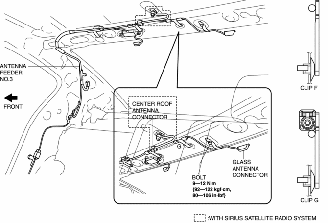
11. Disconnect the glass antenna connector..
12. Remove the bolt.
13. Remove the clips F and G.
14. Install in the reverse order of removal.
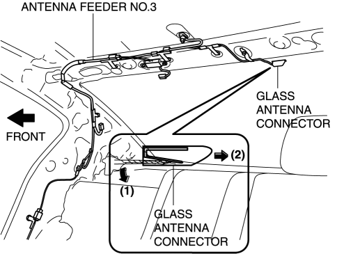
Glass Antenna Connector Removal Note
1. Remove the connector B in the direction of the arrow (2) shown in the figure while pressing the glass antenna terminal in the direction of the arrow (1).
5HB
With audio unit (without display)
1. Disconnect the negative battery cable..
2. Remove the rain sensor cover. (Vehicles with auto light/wiper system).
3. Disconnect the rain sensor connector. (Vehicles with auto light/wiper system)
4. Partially peel back the seaming welts.
5. Remove the following parts:
a. Sunroof seaming welt (vehicles with sunroof)
b. A-pillar trim.
c. Front scuff plate.
d. Rear scuff plate.
e. B-pillar lower trim.
f. Upper anchor of the front seat belt.
g. B-pillar upper trim.
h. Rear seat cushion.
i. Tire house trim.
j. Trunk side upper trim.
k. C-pillar trim.
l. Map light.
m. Sunvisor.
n. Assist handle.
o. Headliner.
6. Disconnect the connector.
7. Remove the clips A and B.
8. Remove the antenna feeder No.3.
9. Install in the reverse order of removal.
With audio unit (with display)
1. Disconnect the negative battery cable..
2. Remove the rain sensor cover. (Vehicles with auto light/wiper system).
3. Disconnect the rain sensor connector. (Vehicles with auto light/wiper system)
4. Partially peel back the seaming welts.
5. Remove the following parts:
a. Sunroof seaming welt (vehicles with sunroof)
b. A-pillar trim.
c. Front scuff plate.
d. Rear scuff plate.
e. B-pillar lower trim.
f. Upper anchor of the front seat belt.
g. B-pillar upper trim.
h. Rear seat cushion.
i. Tire house trim.
j. Trunk side upper trim.
k. C-pillar trim.
l. Map light.
m. Sunvisor.
n. Assist handle.
o. Headliner.
p. Liftgate upper trim.
6. Disconnect the antenna feeder No.7..
7. Disconnect the antenna feeder No.5.
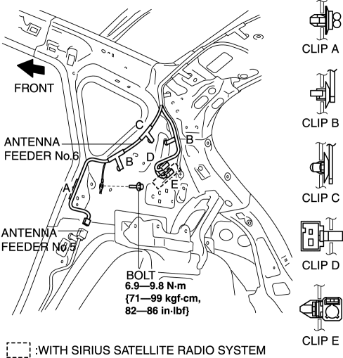
8. Remove the clips A, B, C, D and E.
9. Remove the bolt.
10. Disconnect the connector.
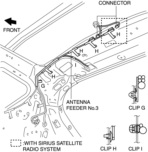
11. Remove the clips G, H, and I.
12. Remove the antenna feeder No.3.
13. Install in the reverse order of removal.
 Antenna Feeder No.3 Inspection
4SD (With Audio System (With Display))
1. Disconnect the negative battery cable..
2. Remove the rain sensor cover. (Vehicles with auto light/wiper system).
3. Disconnect the rain sensor connector ...
 Antenna Feeder No.4 Inspection
1. Disconnect the negative battery cable..
2. Remove the following parts:
a. Upper column cover.
b. Instrument cluster.
c. Center panel.
d. Audio unit (Vehicles with audio unit).
e. Center ...
Other materials:
PID/Data Monitor Inspection [Blind Spot Monitoring (Bsm)]
1. Connect the M-MDS (IDS) to the DLC-2.
2. After the vehicle is identified, select the following items from the initialization
screen of the IDS.
a. Select “DataLogger”.
b. Select “Modules”.
c. Select “BSML” or “BSMR”.
3. Select the applicable PID from the PID table.
4. Verify the ...
Error Indications (Type A)
If you see an error indication on the
display, find the cause in the chart. If you
cannot clear the error indication, take the
vehicle to an Authorized Mazda Dealer.
Indication
Cause
Solution
CHECK
USB
USB device
malfunction
Verify that the content
...
Drive Shaft Inspection
1. Inspect the connections for any looseness.
If there is any malfunction, tighten or replace the applicable part.
2. Inspect the dust boot for damage and cracks.
If there is any malfunction, replace the applicable part.
3. Move the spline and joint up and down, left ...
