Mazda 3 Service Manual: Antenna Feeder No.7 Removal/Installation
1. Disconnect the negative battery cable..
2. Remove the liftgate upper trim..
3. Disconnect the connector A.
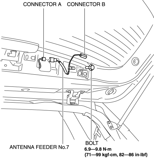
4. Disconnect the connector B..
5. Remove the bolt.
6. Remove the antenna feeder No.7.
7. Install in the reverse order of removal.
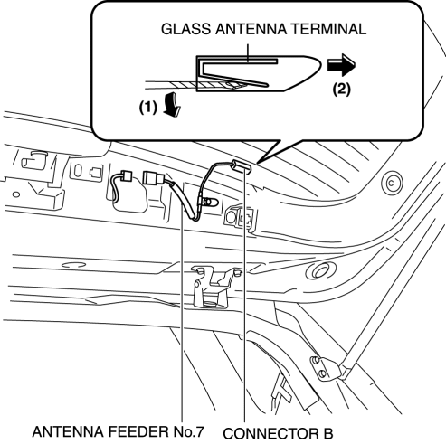
Connector B Removal Note
1. Remove the connector B in the direction of the arrow (2) shown in the figure while pressing the glass antenna terminal in the direction of the arrow (1).
 Antenna Feeder No.7 Inspection
1. Disconnect the negative battery cable..
2. Remove the liftgate upper trim..
3. Disconnect the connector A and B..
4. Verify that the continuity between antenna feeder No.7 terminals is as ind ...
 Audio Amplifier Removal/Installation
1. Slide the passenger seat rearward.
2. Remove the cover.
3. Remove the bolt.
4. Detach the clips and set the vehicle wiring harness aside.
5. Slide the passenger seat forward.
6. Disco ...
Other materials:
Seat Warmer Unit Removal/Installation
Removal
WARNING:
Handling a front seat (with built-in side air bag) improperly can accidentally
operate (deploy) the air bag, which may seriously injure you. Read the service
warnings before handling a front seat (with built-in side air bag)..
CAUTION:
After removing a f ...
Clutch Pedal Position (CPP) Switch Inspection [Mzr 2.0, Mzr 2.5]
Continuity Inspection
1. Verify that the CPP switch is installed properly..
2. Remove the battery cover..
3. Disconnect the negative battery cable..
4. Disconnect the CPP switch connector..
5. Verify that the continuity between CPP switch terminals A and B when the clutch
pedal is depress ...
Front Combination Light Removal/Installation
WARNING:
Incorrect servicing of the discharge headlights could result in electrical
shock. Before servicing the discharge headlights, always refer to the discharge
headlight service warnings..
1. Disconnect the negative battery cable..
2. Remove the front bumper..
3. Disconne ...
