Mazda 3 Service Manual: Blower Motor Removal [Manual Air Conditioner]
NOTE:
-
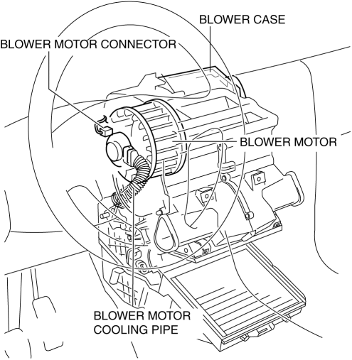
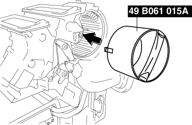
The blower motor is located on the A/C unit as shown in the figure.
-
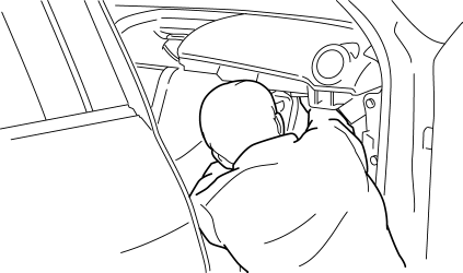
Perform the work from the front passenger side in the posture shown in the figure.
1. Set the air intake mode to FRESH.
2. Disconnect the negative battery cable.
3. Remove the following parts:
a. Front scuff plate.
b. Front side trim.
c. Upper panel.
d. Shift lever knob (MTX).
e. Selector lever knob (ATX).
f. Shift panel.
g. Side wall.
h. Console.
i. Dashboard under cover.
j. Glove compartment.
k. Hood release lever.
l. Lower panel.
m. Shower duct (passenger-side).
n. Accelerator pedal.
4. Disconnect the air intake actuator connector..
5. Detach the harness clip from the blower case.
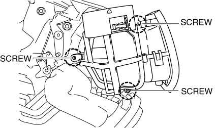
6. Remove the screws shown in the figure and slide the blower case.
7. Remove the blower case.
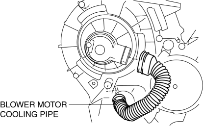
8. Disconnect the blower motor cooling pipe.
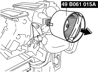
9. Install the SST (49 B061 015A)
to the blower motor.
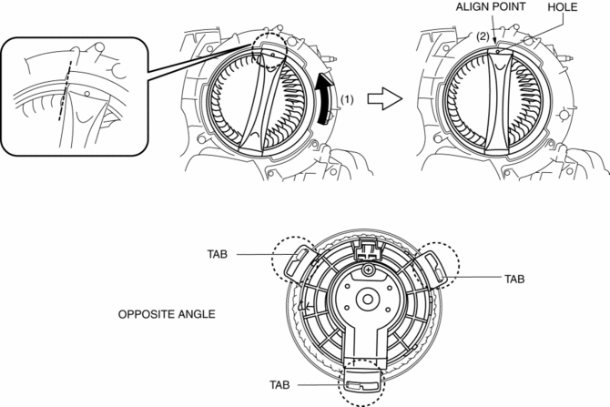
10. Rotate the SST
(1) and align the SST
hole with the align point (2) and then confirm that the SST
tabs into the three set holes on the blower motor they are inserted as shown in the figure.
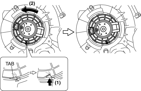
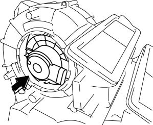
11. Press the tab (1) and rotate the blower motor (2) and push the blower motor into the A/C case slightly.
12. Rotate the blower motor and the blower motor connector position as shown in the figure (3) for disconnect the blower motor connector eased.
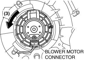
13. Press the tab (4) and disconnect the blower motor connector as shown in the figure (5).
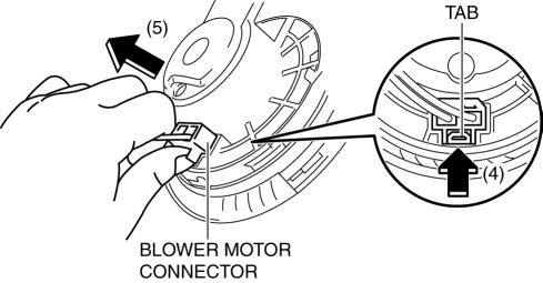
14. Remove the blower motor in the direction shown by the arrow.
CAUTION:
-
To prevent damage to the sirocco fan, pull the blower motor out being careful that the blower motor does not interfere with the A/C unit.
15. Remove the blower motor with SST (49 B061 015A)
by pulling it out.
CAUTION:
-
To prevent damage to the sirocco fan, pull the blower motor out being careful that the blower motor does not interfere with the A/C unit.
 Blower Motor Removal [Full Auto Air Conditioner]
NOTE:
The blower motor is located on the A/C unit as shown in the figure.
Perform the work from the front passenger side in the posture shown in the
figure.
1. Set ...
 Climate Control Unit Disassembly/Assembly [Manual Air Conditioner]
1. Disassemble in the order indicated in the figure.
1
Dial
2
Airflow mode wire
(See Wire Removal Note.)
(See Wire Installation Note.)
...
Other materials:
Automatic air conditioning system
In the Subaru Solterra, the automatic air conditioning system intelligently
regulates airflow distribution and fan speed in real time, ensuring that the interior
climate remains consistent with the selected temperature settings for maximum comfort
and efficiency.
Air conditioning controls
...
Hazard Warning Switch Removal/Installation
1. Disconnect the negative battery cable..
2. Remove the center panel..
3. Remove in the order indicated in the table.
1
Screw
2
Hazard warning switch
4. Install in the reverse order of removal. ...
Sirius Satellite Radio Unit Removal/Installation
1. Disconnect the negative battery cable..
2. Remove the following parts:
a. Passenger-side front scuff plate.
b. Passenger-side front side trim.
c. Dashboard under cover.
d. Grove compartment.
e. Passenger-side lower panel.
3. Remove in the order indicated in the table.
...
