Mazda 3 Service Manual: Body Control Module (Bcm) Removal/Installation
CAUTION:
-
When replacing the BCM, the configuration procedure must be performed before removing the BCM. Replacing the BCM without performing the configuration procedure will result in system malfunction.
ATX
1. Perform the BCM configuration when replacing it..
2. Disconnect the negative battery cable..
3. Remove the following parts:
a. Front scuff plate (LH).
b. Front side trim (LH).
c. Upper panel.
d. Selector lever knob.
e. Shift panel.
f. Side wall.
g. Console.
4. Set the hood release lever out of the way..
5. Remove the lower panel. (driver-side).
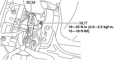
6. Remove the nut shown in the figure.
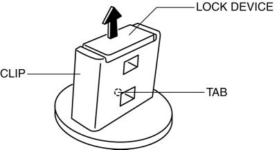
7. Pry off the lock device of the clip while pressing the tab in the position shown in the figure.
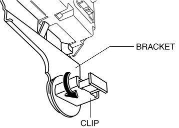
8. Rotate the clip in the direction of the arrow shown in the figure.
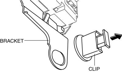
9. Remove the clip by pulling it in the direction of the arrow shown in the figure.
10. Disconnect the connector shown in the figure.
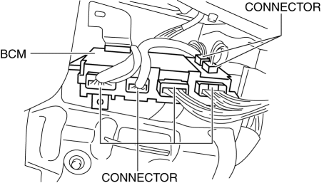
11. While pressing the tab shown in the figure, pull the bracket in the direction of the arrow and remove it.
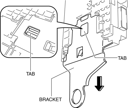
12. Remove the BCM.
13. Install in the reverse order of removal.
MTX
1. Perform the BCM configuration when replacing it..
2. Disconnect the negative battery cable..
3. Remove the following parts:
-
Front scuff plate (LH).
-
Front side trim (LH).
-
Upper panel.
-
Shift knob.
-
Shift panel.
-
Side wall.
-
Console.
4. Set the hood release lever out of the way..
5. Remove the lower panel. (driver-side).
6. Remove the starter cut relay. (with advanced keyless entry and push button start system).
7. Remove the nuts shown in the figure.
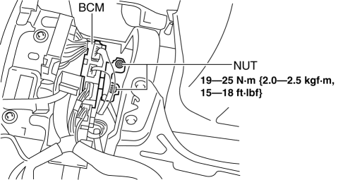
8. Pry off the lock device of the clip while pressing the tab in the position shown in the figure.

9. Rotate the clip in the direction of the arrow shown in the figure.

10. Remove the clip by pulling it in the direction of the arrow shown in the figure.

11. Disconnect the connector shown in the figure.

12. While pressing the tab shown in the figure, pull the bracket in the direction of the arrow and remove it.

13. Remove the BCM.
14. Install in the reverse order of removal.
 Body Control Module (Bcm) Inspection
1. Remove the following parts:
a. Front scuff plate (LH).
b. Front side trim (LH).
c. Upper panel.
d. Shift knob (MTX).
e. Selector lever knob (ATX).
f. Shift panel.
g. Side wall.
h. C ...
 Controller Area Network (Can) System
Outline
With the addition of the following, the system wiring diagram and CAN communication
table have been added.
USB adapter
System Wiring Diagram
CAN Signal ...
Other materials:
Power Brake Unit Inspection
NOTE:
The following inspection methods are simple inspection methods to judge the
function of the power brake unit.
If there is any malfunction in the power brake unit, replace the power brake
unit as a single unit.
Without Using SST
Operation inspection
1. With the eng ...
Steering Switch Removal/Installation
WARNING:
Handling the air bag module improperly can accidentally deploy the air bag
module, which may seriously injure you. Read the air bag system service warnings
and cautions before handling the air bag module..
1. Disconnect the negative battery cable and wait for 1 min or mo ...
Vacuum Pump Inspection [Skyactiv G 2.0]
1. Pinch open the clamp using pliers and disconnect the vacuum hose from the
vacuum pump.
2. Install the vacuum gauge as shown in the figure, then check the vacuum.
3. Warn up the engine.
If the pressure is less than the specification, inspect for the following.
M ...
