
Mazda 3 Service Manual: Floor Under Cover Removal/Installation
1. Lift up the vehicle.
2. Remove the cap nuts.
3. Remove the nus.
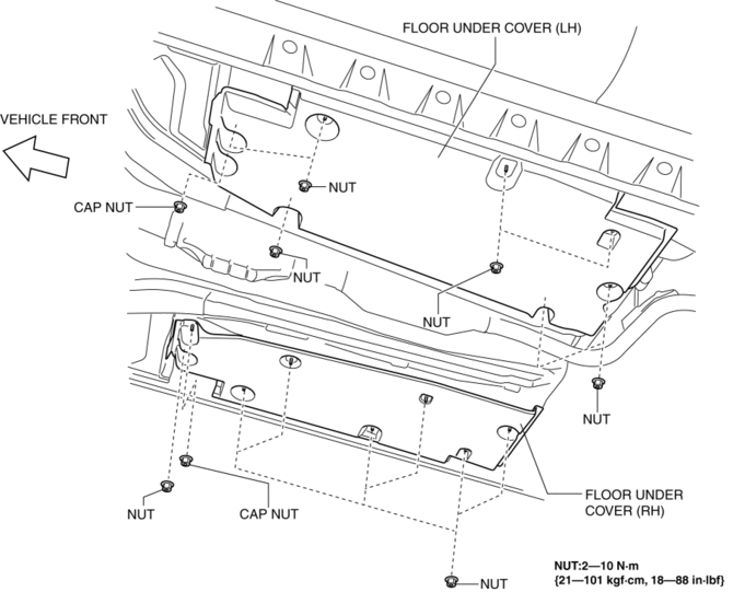
4. Pull the floor under covers in the direction of arrow (1), (2), (3) shown in the figure, and then remove it.
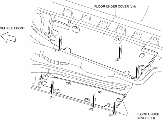
5. Install in the reverse order of removal.
 Extractor Chamber Removal/Installation
1. Disconnect the negative battery cable..
2. Remove the rear combination light..
3. Remove the rear bumper..
4. Remove the clips.
5. Install in the reverse order of removal. ...
 Front Beltline Molding Removal/Installation
1. Fully open the front door glass.
2. Disconnect the negative battery cable..
3. Remove the inner garnish..
4. Remove the front door trim..
5. Remove the power outer mirror..
6. Remove clip ...
Other materials:
Headlight switch
In the Subaru Solterra, the headlight system can be controlled either
manually or automatically, offering flexibility and intelligent adaptation to changing
driving conditions.
Turning on the headlights
By operating
the switch, the lighting system of the Subaru Solterra activates in differ ...
Plastic Part Maintenance
When cleaning the plastic lenses of the
lights, do not use gasoline, kerosene,
rectified spirit, paint, thinner, highly
acidic detergents, or strongly alkaline
detergents. Otherwise, these chemical
agents can discolor or damage the
surfaces resulting in a significant loss
in functio ...
Reading this manual
Explains symbols used in this manual
Symbols in this manual
WARNING:
In the Subaru Solterra Owner’s Manual, this symbol highlights
critical information that must be followed without exception. Ignoring such instructions
may result in severe injury or even loss of life. Always pay close ...
