
Mazda 3 Service Manual: Forced Ignition On [With Advanced Keyless Entry And Push Button Start System]
NOTE:
-
In order to perform a forced ignition ON, the M-MDS (IDS) is necessary. If the servicing is being done outside of an Authorized Mazda dealership, contact an Authorized Mazda dealership for instructions.
-
The forced ignition ON procedure forces a power supply to each part when no power is available even after the ignition switch has been operated. However, the engine cannot be started and the steering cannot be unlocked.
-
When performing a forced ignition ON procedure, remove all advanced keys from the vehicle. If an advanced key is left in the vehicle, the forced ignition ON procedure cannot be done.
1. Verify that there are no advanced keys in the vehicle.
2. Get PCM part number from As-built site.
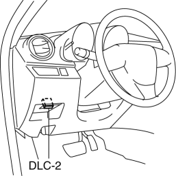
3. Connect the M-MDS (IDS) to the DLC-2.
4. Manual vehicle identification.
-
Select “Manual Vehicle Entry”.
5. Select the “All other” from Vehicle list.
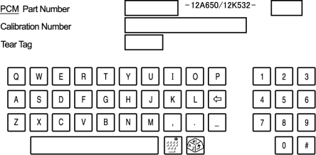
6. Input the PCM part number on the following screen.
7. After the vehicle is identified, select the following items from the initialization screen of the IDS.
-
Select “Body”.
-
Select “Special Ignition ON”.
8. Perform the procedure according to the directions on the screen.
9. Delete session with keeping ignition ON.
10. Normal vehicle identification.
 Ignition
...
 Ignition Coil Inspection [Mzr 2.0, Mzr 2.5]
Ignition Coil Inspection
1. Perform the spark test and identify the malfunctioning cylinder..
2. Replace the ignition coil of the malfunctioning cylinder with that of a normal
cylinder, and perfo ...
Other materials:
Antenna Feeder No.3 Removal/Installation
4SD (With Audio Unit (With Display))
1. Disconnect the negative battery cable..
2. Remove the rain sensor cover. (Vehicles with auto light/wiper system).
3. Disconnect the rain sensor connector. (Vehicles with auto light/wiper system)
4. Partially peel back the seaming welts.
5. Remove the ...
Positive Crankcase Ventilation (PCV) Valve Inspection [Mzr 2.0, Mzr 2.5]
Airflow Inspection
1. Disconnect the section (A) of the ventilation hose shown in the figure.
2. Start the engine and verify that vacuum is applied to the end of the disconnected
ventilation hose while the engine is idling.
NOTE:
Because it is difficult to directly inspect the PC ...
Troubleshooting
Mazda Bluetooth ® Hands-Free Customer Service
If you have any problems with Bluetooth ® , contact our toll-free customer
service center.
U.S.A.
Canada
Mexico
Bluetooth ® Device pairing, connection problems
*1 Setting which detects the existence of a device external to the Bluet ...
