Mazda 3 Owners Manual: Luggage Compartment
Luggage compartment cover (5-door)
| WARNING
Do not place anything on top of the
cover:
Placing luggage or other cargo on top
of the luggage compartment cover is
dangerous. During sudden braking or
a collision, the cargo could become
a projectile that could hit and injure
someone. The vehicle has a light
weight luggage compartment cover to
keep the contents of your luggage area
out of sight; it will not retain heavy
objects that are not tied down in an
accident such as a rollover. Tie down
all heavy objects, whether luggage or
cargo, using the tie down hooks.
Make sure luggage and cargo are secured before driving: Not securing cargo while driving is dangerous as it could move or be crushed during sudden braking or a collision and cause injury. |
| CAUTION Make sure the luggage compartment cover is fi rmly secured. If it is not fi rmly secured, it could unexpectedly disengage resulting in injury. |
The luggage compartment can be accessed by opening the liftgate when the straps are attached to the sides of the liftgate.
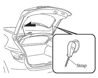
Removing the cover
This cover can be removed for more room.
- Remove the straps from the hooks.
- Lift the end of the luggage compartment cover a little, pull it outward, and remove it from the pins.
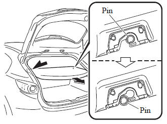
- Lift the front end of the luggage compartment cover and remove it.
Loading golf bags (only 4-door vehicle)
Up to two golf bags can be carried in the trunk.
- Place the bottom of the first golf bag in the trunk with its bottom pointed to the left and fit it into the front of the trunk.
- Place the second golf bag in the trunk with its bottom pointed to the left and fit it into the back of the trunk.
NOTE Some golf bags cannot fit depending on their size.
 Opening and Closing the Liftgate/
Trunk Lid
Opening and Closing the Liftgate/
Trunk Lid
Opening the liftgate (5–door)
Using the electric liftgate opener
Unlock the doors and liftgate, then press
the electric liftgate opener on the liftgate
and raise it when the latch releases.
...
 Inside Trunk Release Lever
(4-Door)
Inside Trunk Release Lever
(4-Door)
Your vehicle is equipped with an inside
trunk release lever that provides a means
of escape for children and adults in the
event they become locked inside the trunk.
No matter how careful adults ...
Other materials:
Starter Interlock Switch Inspection [Mzr 2.0, Mzr 2.5]
CAUTION:
Do not reuse the starter interlock switch if it is removed from the vehicle
even once. Replace with a new starter interlock switch when installing.
1. Remove the battery cover..
2. Disconnect the negative battery cable..
3. Disconnect the starter interlock switch connec ...
Air Cleaner Element Inspection [Mzr 2.0, Mzr 2.5]
1. Remove the air cleaner element..
2. Inspect the following items:
Has the replacement interval come?
Is the air cleaner element soiled, damaged, or bent?
Are the air cleaner case and the air cleaner element correctly sealed?
Is the correct air cleaner element inst ...
Oil Pressure Inspection [Mzr 2.0, Mzr 2.5]
WARNING:
Hot engines and engine oil can cause severe burns. Turn off the engine and
wait until it and the engine oil have cooled.
A vehicle that is lifted but not securely supported on safety stands is dangerous.
It can slip or fall, causing death or serious injury. Never work ...
