
Mazda 3 Service Manual: Magnetic Clutch Disassembly/Assembly [Full Auto Air Conditioner]
1. Disassemble in the order indicated in the table.
SKYACTIV-G 2.0
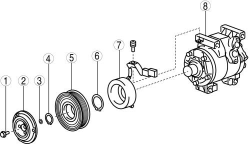
|
1 |
Bolt (See Bolt Removal/Installation Note.) |
|
2 |
Pressure plate |
|
3 |
Shim (See Shim Installation Note.) |
|
4 |
Snap ring (See Snap Ring Removal/Installation Note.) |
|
5 |
A/C compressor pulley |
|
6 |
Snap ring (See Snap Ring Removal/Installation Note.) |
|
7 |
Stator |
|
8 |
A/C compressor body |
MZR 2.3 DISI Turbo, MZR 2.5
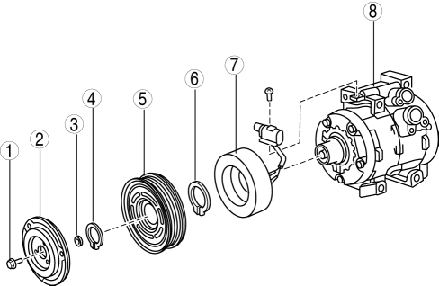
|
1 |
Bolt (See Bolt Removal/Installation Note.) |
|
2 |
Pressure plate |
|
3 |
Shim (See Shim Installation Note.) |
|
4 |
Snap ring (See Snap Ring Removal/Installation Note.) |
|
5 |
A/C compressor pulley (See A/C Compressor Pulley Removal Note.) (See A/C Compressor Pulley Installation Note.) |
|
6 |
Snap ring (See Snap Ring Removal/Installation Note.) |
|
7 |
Stator |
|
8 |
A/C compressor body |
2. Assemble in the reverse order of disassembly.
3. Adjust the magnetic clutch clearance..
Bolt Removal/Installation Note
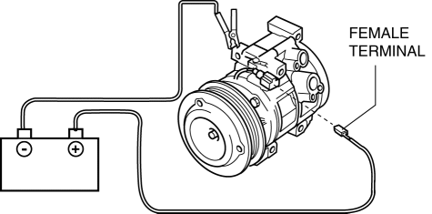
1. When removing or installing the bolt, lock the A/C compressor pulley against rotation using the following procedure.
CAUTION:
-
When connecting the positive battery cable to the magnetic clutch connector, use a cable with a female terminal of the correct size. Otherwise, load will be applied to the terminal, resulting in deformation or damage, and poor contact. In addition, the positive battery cable could disconnect from the connector resulting in a short circuit.
a. Apply battery positive voltage to the magnetic clutch terminal and connect the A/C compressor body to the ground.
b. Wrap the drive belt, which is no longer of use, tightly around the A/C compressor pulley.
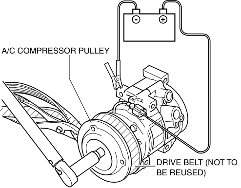
c. Hold the drive belt in place with pliers.
d. Remove/installation the bolt.
-
Tightening torque
-
15 N·m {1.5 kgf·m, 11 ft·lbf}
2. When installing a new A/C compressor body, replace the recommended bolt.
A/C Compressor Pulley Removal Note
1. Remove the A/C compressor pulley using the SSTs
(49 0839 425C, 49 SE01 160).
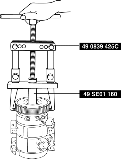
CAUTION:
-
Be careful that the SST (49 0839 425C) tabs do not hang over the stator.
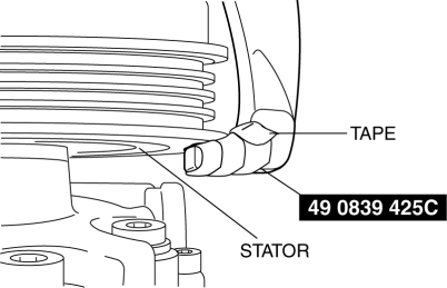
NOTE:
-
Place on the tape to prevent damage.
A/C Compressor Pulley Installation Note
1. Install the inner wheel of the pulley using SST
(49 D034 202) to the compressor.
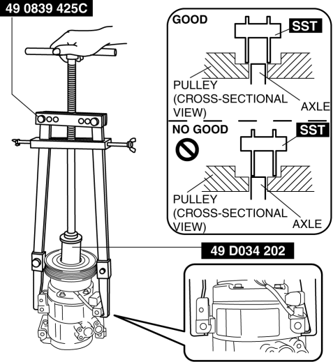
CAUTION:
-
If the SST is not properly positioned when the A/C compressor pulley is press-fit, the A/C compressor axle will interfere with the SST, possibly damaging component parts. Verify the SST and axle are properly positioned and perform the procedure very carefully.
Snap Ring Removal/Installation Note
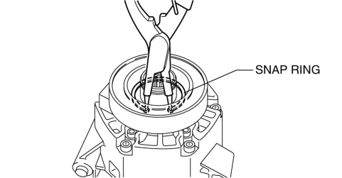
1. Remove/install the snap ring using a snap ring pliers.
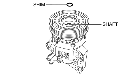
Shim Installation Note
1. First, insert the 1mm (0.039 in)
thick shim into the shaft.
 Magnetic Clutch Adjustment [Manual Air Conditioner]
1. Measure the clearance around the entire circumference between the pressure
plate and A/C compressor pulley using a thickness gauge.
2. Verify that the clearance.
If not within the s ...
 Magnetic Clutch Disassembly/Assembly [Manual Air Conditioner]
1. Disassemble in the order indicated in the table.
SKYACTIV-G 2.0
1
Bolt
(See Bolt Removal/Installation Note.)
2
Pressure plate
...
Other materials:
Rear Seat Back Frame Removal/Installation
1. Remove the rear seat cushion..
2. Remove the rear buckle installation bolt..
3. Remove the rear seat back..
4. Remove the headrest.
5. Open the fasteners.
6. Detach the hooks.
7. Remove the child-restraint seat anchor covers in the order of (1), (2) as
shown in the figure. (5H ...
Boost Air Temperature Sensor Inspection [Mzr 2.3 Disi Turbo]
Resistance Inspection
NOTE:
Because the boost air temperature sensor is integrated in the MAP sensor,
replacing the boost air temperature sensor includes replacement of the MAP sensor/boost
air temperature sensor.
1. Remove the battery cover..
2. Disconnect the negative batter ...
Locking, Unlocking with Door-
Lock Knob
Operation from inside
To lock any door from the inside, press the
door-lock knob.
To unlock, pull it outward.
This does not operate the other door locks.
NOTE
The red indication can be seen when the
door-lock knob is unlocked.
Operation from outside
To lock the rear and front pa ...
