Mazda 3 Service Manual: Rear Spoiler Removal/Installation
4SD
1. Remove the trunk lid trim..
2. Remove the nuts.

3. While cutting the double-sided adhesive tape using a flathead screwdriver or a razor, separate the rear spoiler from the trunk lid.
WARNING:
-
Using a razor with bare hands can cause injury. Always wear gloves when using a razor.
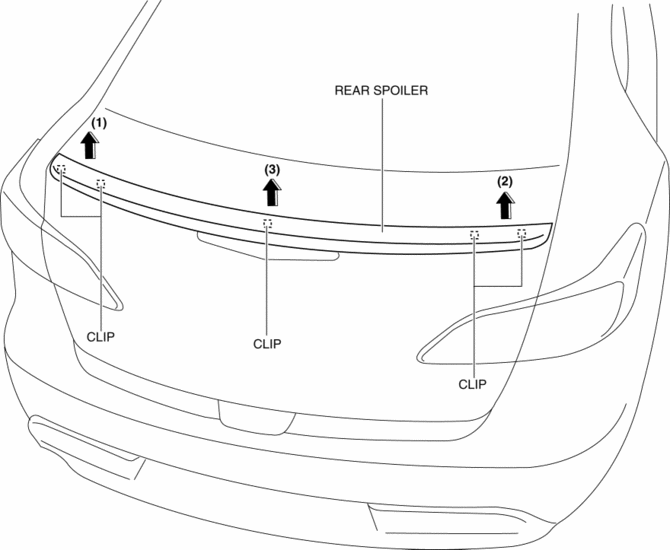
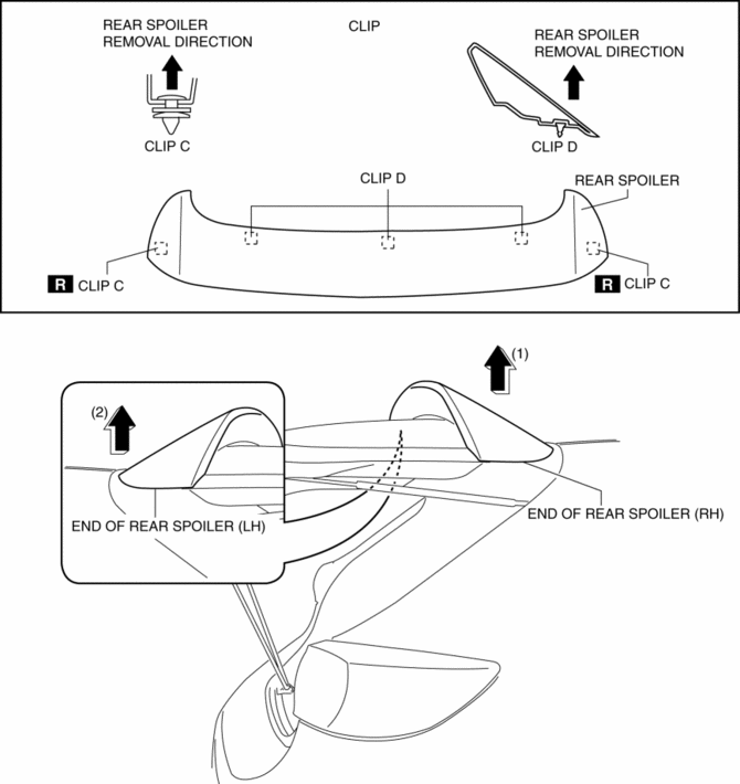
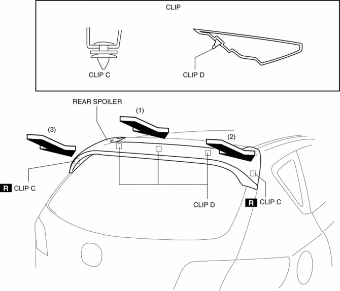
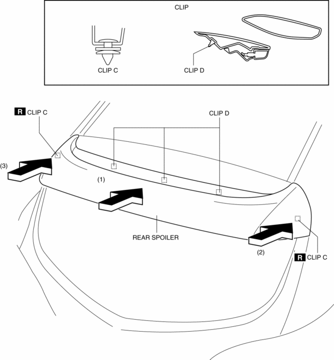
4. Pull the rear spoiler in the direction of arrow in the order of (1), (2) and (3), then remove the clips from the trunk lid.
5. Remove the rear spoiler.
6. Install in the reverse order of removal.
NOTE:
-
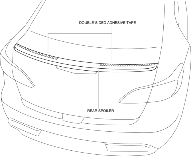
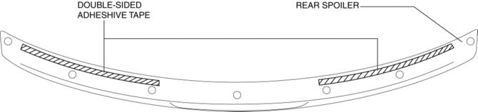
Attach double–sided adhesive tape to the rear spoiler as shown in the figure.
5HB (Except MPS)
Removal
1. Disconnect the negative battery cable.
2. Remove the following parts:
a. Liftgate upper trim.
b. Liftgate side trim.
c. Liftgate lower trim.
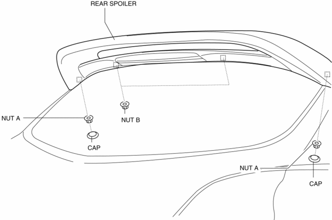
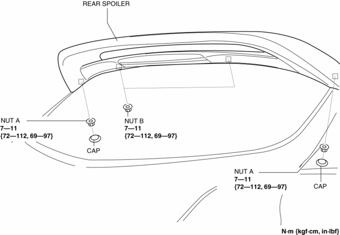
3. Remove the caps.
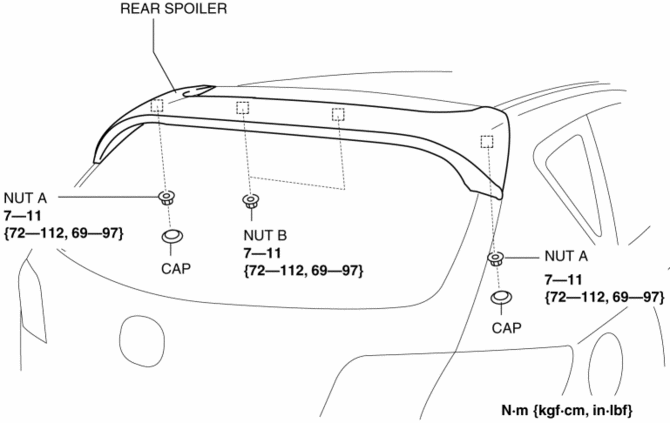
4. Remove the nut A and B.
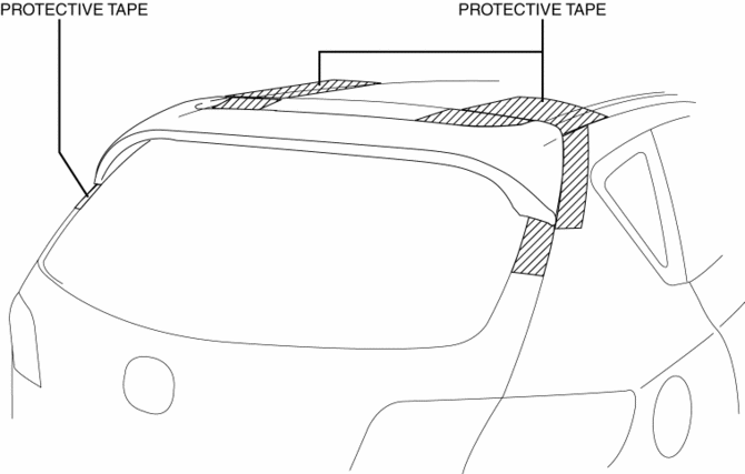
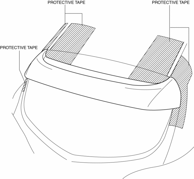
5. Affix protective tape to the position shown in the figure.
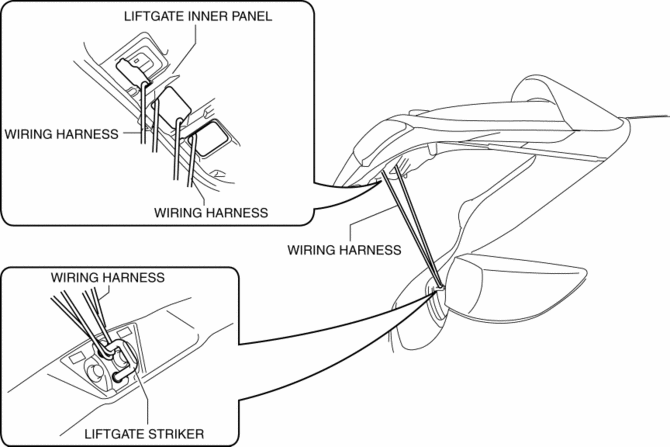
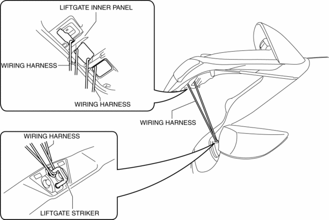
6. The wiring harness install on the liftgate inner panel with lift gate striker, and the liftgate is fixed while half opened.
7. Pull up the end of rear spoiler in the direction of the arrow in the order of (1), (2) and remove the rear spoiler while detaching the clips C and D.
8. Remove the rear spoiler.
WARNING:
-
When removing the rear spoiler clips, the liftgate may bounce up by its rebound and cause injury. Remove the rear spoiler clip avoiding the range of movement of the liftgate.
CAUTION:
-
When removing the rear spoiler clips, the rear spoiler may fall off by its rebound and be damaged. Perform the rear spoiler clip removal using two people.
Installation
WARNING:
-
If the rear spoiler clip installation is performed with the liftgate fully or half opened, the liftgate may accidentally close or bounce up, leading to injury. Perform the rear spoiler clip installation with the liftgate fully closed.
NOTE:
-
To facilitate the procedure after rear spoiler installation, peel the protective tape adhered during removal before installing the rear spoiler.
1. If the rear spoiler is to be reused, perform the following procedure:
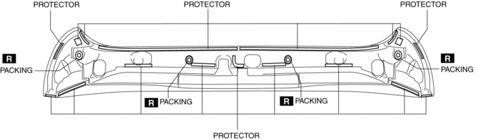
a. Remove the packing and protector remaining on the rear spoiler after removal.
b. Remove any grease and dirt from the packing and protector affixing area.
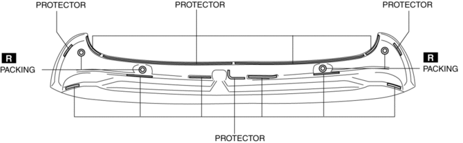
c. Affix packing and protector to the position shown in the figure.
d. If the protector is damaged, replace the part that is damaged with a new protector.
2. Push the rear spoiler in the direction of the arrow in the order of (1), (2), (3) and install the rear spoiler while install the clips C and D.
3. Open the liftgate.
4. Install the nuts A and B.
5. Install the caps.
6. Install the following parts:
a. Liftgate lower trim.
b. Liftgate side trim.
c. Liftgate upper trim.
7. Connect the negative battery cable..
5HB (MPS)
Removal
1. Disconnect the negative battery cable.
2. Remove the following parts:
a. Liftgate upper trim.
b. Liftgate side trim.
c. Liftgate lower trim.
3. Remove the caps.
4. Remove the nut A and B.
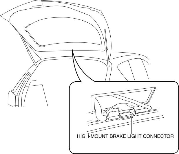
5. Disconnect the high-mount brake light connector.
6. Affix protective tape to the position shown in the figure.
7. The wiring harness install on the liftgate inner panel with lift gate striker, and the liftgate is fixed while half opened.
8. Pull up the end of rear spoiler in the direction of the arrow in the order of (1), (2) and remove the rear spoiler while detaching the clips C and D.
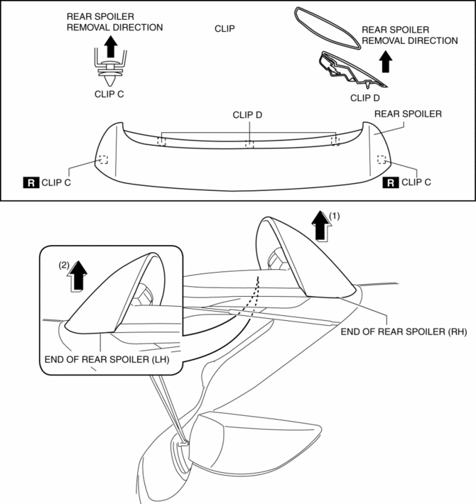
9. Remove the rear spoiler.
WARNING:
-
When removing the rear spoiler clips, the liftgate may bounce up by its rebound and cause injury. Remove the rear spoiler clip avoiding the range of movement of the liftgate.
CAUTION:
-
When removing the rear spoiler clips, the rear spoiler may fall off by its rebound and be damaged. Perform the rear spoiler clip removal using two people.
Installation
WARNING:
-
If the rear spoiler clip installation is performed with the liftgate fully or half opened, the liftgate may accidentally close or bounce up, leading to injury. Perform the rear spoiler clip installation with the liftgate fully closed.
NOTE:
-
To facilitate the procedure after rear spoiler installation, peel the protective tape adhered during removal before installing the rear spoiler.
1. If the rear spoiler is to be reused, perform the following procedure:
a. Remove the packing and protector remaining on the rear spoiler after removal.
b. Remove any grease and dirt from the packing and protector affixing area.
c. Affix packing and protector to the position shown in the figure.
d. If the protector is damaged, replace the part that is damaged with a new protector.
2. Push the rear spoiler in the direction of the arrow in the order of (1), (2), (3) and install the rear spoiler while install the clips C and D.
3. Open the liftgate.
4. Install the nuts A and B.
5. Install the caps.
6. Connect the high-mount brake light connector.
7. Install the following parts:
a. Liftgate lower trim.
b. Liftgate side trim.
c. Liftgate upper trim.
8. Connect the negative battery cable..
 Rear Bumper Removal/Installation
4SD
1. Disconnect the negative battery cable..
2. Remove the rear combination light..
3. Remove the fastener A and screw B.
4. Remove the rear splash shield..
5. Remove the screws C.
...
 Seal Plate Removal/Installation
1. Disconnect the negative battery cable..
2. Remove the front bumper..
3. Remove the bolt.
4. Pull the seal plate in the direction of arrow shown in the figure, then remove
the hook.
...
Other materials:
Seat Weight Sensor Inspection [Two Step Deployment Control System]
CAUTION:
If any of the following work is performed, perform the seat weight sensor
inspection using the M-MDS.
Removal of the passenger-side seat
Loosening and retightening of passenger’s seat fixing bolts
Or, the vehicle is involved in a collision
...
Oil Seal (Differential) Replacement [A26 M R]
1. On level ground, jack up the vehicle and support it evenly on safety stands.
2. Drain the oil from the transaxle..
3. Remove the front tires..
4. Remove the splash shield..
5. Remove the aerodynamic under cover No.2..
6. Separate the drive shaft and joint shaft from the transaxle..
7 ...
Hood
Opening the hood
1. Потягніть важіль відкривання капота в салоні
Subaru Solterra.
Капот трохи підніметься.
2. Перемістіть додатковий фіксатор вліво та
підніміть капот.
3. ...
