Mazda 3 Service Manual: Control Valve Body Removal/Installation [Fw6 A EL]
On-Vehicle Removal
WARNING:
-
A hot transaxle and ATF can cause severe burns. Turn off the engine and wait until they are cool.
-
Using compressed air can cause dirt and other particles to fly out, causing injury to the eyes. Wear protective eyeglasses whenever using compressed air.
CAUTION:
-
If the control valve body has been replaced, perform initial learning..
-
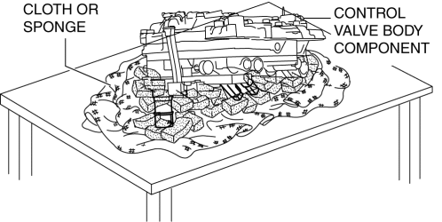
Do not place the control valve body connector pointed downward as the control valve body connector part and sensor could be damaged. If the servicing can only be performed by pointing the control valve body connector downward, spread a large quantity of cloth or sponges on a table and place the control valve body connector part and sensor on the table so that they do not directly contact the table.
1. Select the selector lever to P position.
2. Remove the battery cover..
3. Disconnect the negative battery cable..
4. Remove the aerodynamic under cover No.2..
5. Clean the transaxle exterior throughout with a steam cleaner or cleaning solvents.
6. Remove the air cleaner component..
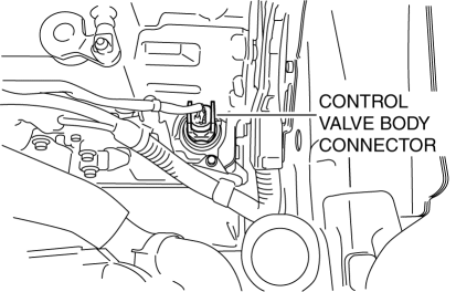
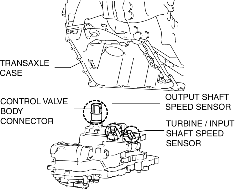
7. Disconnect the control valve body connector.
CAUTION:
-
Make sure that your hand does not touch the terminal as the connector terminal could be damaged.
-
Water or foreign objects entering the connector can cause a poor connection or corrosion. Be sure not to drop water or foreign objects on the connector when disconnecting it.
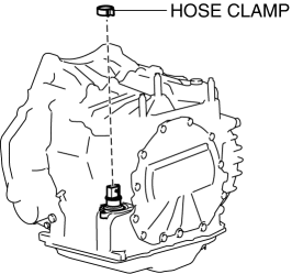
8. Remove the hose clamp.
9. Drain the ATF..
10. Remove the oil pan.
CAUTION:
-
To avoid damaging the control valve body, if there is a large amount of foreign material at the bottom of the oil pan when the oil pan is removed, replace the oil strainer with a new one.
-
If there is not a large amount of foreign material at the bottom of the oil pan, the oil strainer does not have to be replaced.
NOTE:
-
Always use new oil pan installation bolts when re-installing the oil pan because the oil pan installation bolts cannot be reused.
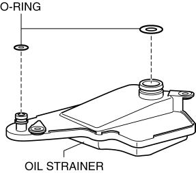
11. Remove the oil strainer.
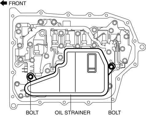
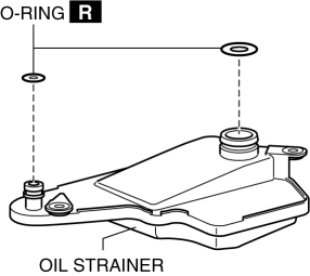
12. Remove the oil strainer O-ring.
13. Remove the control valve body.
CAUTION:
-
Remove the control valve body directly from underneath so that force is not applied to the control valve body connector in the lateral direction.
14. Remove the oil seal (control valve body)..
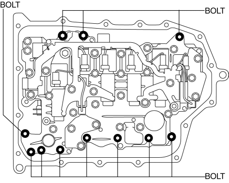
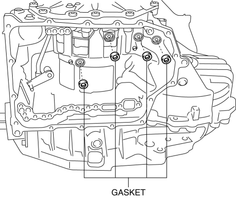
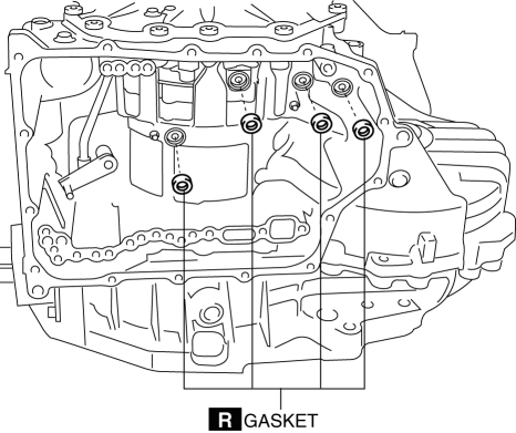
15. Remove the gasket from the transaxle case.
On-Vehicle Installation
1. Install the gasket to the transaxle case.
2. Install the dowel pin to the control valve body.
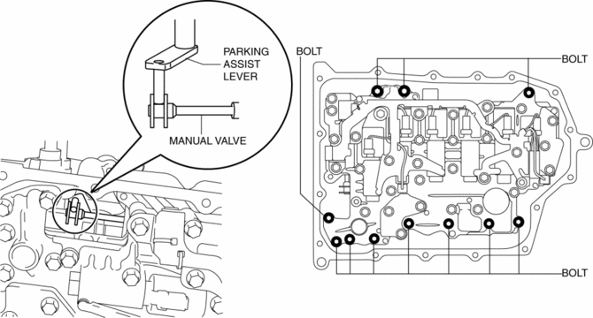
3. Install the control valve body so that the parking assist lever component is engaged in the gap between the spool part of the manual valve.
CAUTION:
-
Install the control valve body so that the parts circled by the dotted line do not contact the transaxle case.
-
Tightening torque
-
9—10 N·m {92—101 kgf·cm, 80—88 in·lbf}
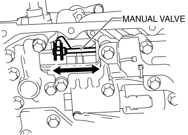
4. Stroke the manual valve in the direction of the arrow to verify that the manual valve is correctly engaged with the parking assist lever component.
NOTE:
-
If the manual valve only moves in the gap between the parking assist lever component surface and the manual valve surface, the manual valve and the parking assist lever component are correctly engaged.
5. Install the oil strainer O-ring.
NOTE:
-
If there is a large amount of foreign material at the bottom of the oil pan, replace the oil strainer with a new one.
6. Install the oil strainer.
-
Tightening torque
-
9—10 N·m {92—101 kgf·cm, 80—88 in·lbf}
7. Apply a light coat of silicon sealant (TB1217E) to the contact surfaces of the oil pan and transaxle case.
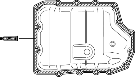
CAUTION:
-
If any sealant remains on the sealing surfaces of the transaxle case and oil pan, transaxle damage may occur. Use a cleaning fluid to remove any old sealant from the transaxle case and oil pan.
8. Install the oil pan with new bolts before the applied sealant starts to harden.
-
Tightening torque
-
8—10 N·m {82—101 kgf·cm, 71—88 in·lbf}
9. Install the aerodynamic under cover No.2..
10. Install the oil seal (control valve body)..
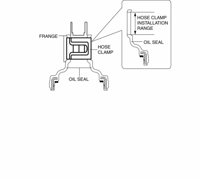
11. Install a new hose clamp to the position shown in the figure.
CAUTION:
-
If the hose clamp is reused it could cause ATF leakage, therefore use a new hose clamp.
-
Install the hose clamp tab to within the range shown in the figure.
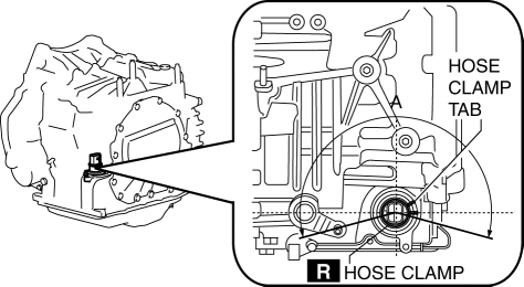
A:210°
CAUTION:
-
Install the hose clamp so that it does not interfere with the top and bottom flanges of the oil seal to maintain the waterproofing integrity.
12. Connect the control valve body connector.
CAUTION:
-
Make sure that your hand does not touch the terminal as the connector terminal could be damaged.
-
Verify that there is no fluid or foreign matter adhering to the connector before connecting the connector.
-
Insert the connector straight as the connector terminal could be damaged.
-
Rotate the connector lever until a click is heard.
13. Add the ATF..
14. Install the air cleaner component..
15. Connect the negative battery cable..
16. Install the battery cover..
17. Perform the “TCM configuration” (Control valve body Replacement)..
18. Perform the “Initial Learning” (Control valve body Replacement)..
19. Perform the “Mechanical System Test”..
20. Perform the “Road Test”..
 Control Valve Body Removal/Installation [FS5 A EL]
Primary Control Valve Body On-Vehicle Removal
WARNING:
A hot transaxle and ATF can cause severe burns. Turn off the engine and wait
until they are cool.
Using compressed air can ca ...
 Coupler Component Removal/Installation [Fw6 A EL]
WARNING:
A hot transaxle and ATF can cause severe burns. Turn off the engine and wait
until they are cool.
Always wear protective eye wear when using the air compressor. If the ...
Other materials:
On Board Diagnostic System PID/Data Monitor Inspection [FS5 A EL]
NOTE:
The PID data screen function is used for monitoring the calculated value
of input/output signals in the module. Therefore, if the monitored value of
the output parts is not within the specification, it is necessary to inspect
the monitored value of input parts corresponding to ...
Identification Numbers
Vehicle Identification Number
The vehicle identification number legally
identifies your vehicle. The number is on a
plate attached to the cowl panel located on
the left corner of the dashboard. This plate
can easily be seen through the windshield
Motor Vehicle Safety Standard Label (U.S.A. ...
Combination Switch Removal/Installation
CAUTION:
Handling the air bag module improperly can accidentally deploy the air bag
module, which may seriously injure you. Read the air bag system service warnings
and cautions before handling the air bag module..
1. Switch the ignition to off.
2. Disconnect the negative batte ...
