Mazda 3 Service Manual: Malfunctioning Wheel Unit Identification
NOTE:
-
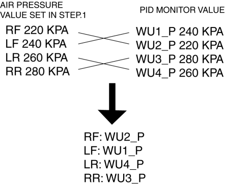
The tire pressure monitoring system (TPMS) does not identify the location of the malfunctioning wheel unit on the vehicle (RF, LF, LR, RR). The TPMS identifies each wheel unit as No.1, No.2, No.3 and No.4. In order to identify the location of the wheel unit, perform the following procedure.
1. Adjust the air pressure as follows:
-
RF: 220 kPa {2.2 kgf/cm2, 32 psi}
-
LF: 240 kPa {2.4 kgf/cm2, 35 psi}
-
LR: 260 kPa {2.6 kgf/cm2, 38 psi}
-
RR: 280 kPa {2.8 kgf/cm2, 40 psi}
2. Switch the ignition to off.
3. Connect the M-MDS to the DLC-2.
4. Switch the ignition to ON.
5. Drive the vehicle at a speed of 25 km/h {15.5 mph} or more
for 2 min or more.
6. Select the following PIDs using the M-MDS, and monitor them.
-
WU1_P
-
WU2_P
-
WU3_P
-
WU4_P
7. Determine which wheel unit identification code matches which wheel and tire by comparing the PID monitor values with the air pressure values set in Step 1.
 Wheels, Tires
...
 Parameter Setting Procedure When Tire Size Is Changed
CAUTION:
If the wheel and tire sizes are changed, a discrepancy with the speedometer
needle whereby it exceeds the allowable range could result in a malfunction.
If the wheel and tire si ...
Other materials:
Hood Release Cable Removal/Installation
1. Disconnect the negative battery cable..
2. Remove the battery tray..
3. Remove the Front mudguard (LH)..
4. Remove the hood release cable from clips A.
5. Remove the clips B.
6. Disconnect the hood latch from the hood release cable.
7. Remove the hood release cable from outside of ...
Glass Panel Adjustment
1. Fully close the glass panel.
2. Measure the gap and height between the glass panel and body.
If not as specified, loosen the glass panel installation screws and reposition
the glass panel.
Clearance (4SD)
a: -2.4—0.2 mm {-0.09—0.01 in}
b: 0 mm {0 in}
...
Sae Standards
In accordance with new regulations, SAE (Society of Automotive Engineers)
standard names and abbreviations are now used in this manual. The table below
lists the names and abbreviations that have been used in Mazda manuals up to
now and their SAE equivalents.
...
