Mazda 3 Service Manual: Service Cautions
Injury/damage Prevention Precautions
-
Depending on the vehicle, the cooling fan may operate suddenly even when the ignition is switched to off. Therefore, keep hands and tools away from the cooling fan even if the cooling fan is not operating to prevent injury to personnel or damage to the cooling fan. Always disconnect the negative battery cable when servicing the cooling fan or parts near the cooling fan.
Protection of the Vehicle
-
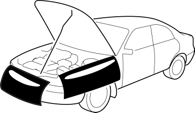
Always be sure to cover fenders, seats and floor areas before starting work.
Preparation of Tools and Measuring Equipment
-
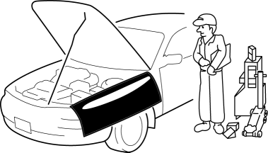
Be sure that all necessary tools and measuring equipment are available before starting any work.
Special Service Tools
-
Use special service tools or equivalent when they are required.
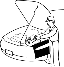
Malfunction Diagnosis System
-
Use the Mazda Modular Diagnostic System (M-MDS) or equivalent for malfunction diagnosis.
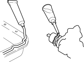
Negative Battery Cable Disconnection/Connection
Warning
-
Before removing the SRS air bag system-related parts, always disconnect the negative battery cable and wait for 1 min. or more to allow the back-up power supply to deplete its stored power.
Negative battery cable disconnection/required procedures after connecting
|
System name |
Conditions after disconnecting the negative battery cable |
Required procedure |
Reference |
||
|
Before disconnecting negative battery cable |
After connecting negative battery cable |
||||
|
Power window system |
Reset to initial setting and auto-function is disabled. |
- |
Perform the power window system initial setting. |
(See POWER WINDOW SYSTEM INITIALIZATION PROCEDURE.) |
|
|
Clock and audio |
Clock display and audio system memory are reset. |
Verify the setting content. |
Set the verified content before disconnecting negative battery cable. |
- |
|
|
Steering angle sensor initialization |
DSC HU/CM |
Reset to initial setting and the system may not operate properly. |
- |
Perform steering angle sensor initialization. |
(See STEERING ANGLE SENSOR INITIALIZATION PROCEDURE.) |
|
AFS control module |
|||||
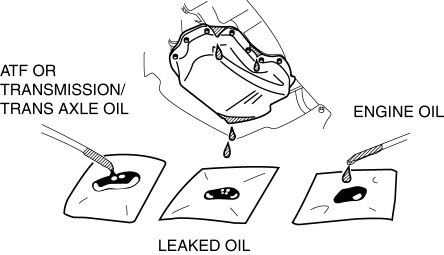
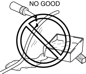
Oil Leakage Inspection
-
Use either of the following procedures to identify the type of oil that is leaking:
Using UV light (black light)
1. Remove any oil on the engine or transmission/transaxle.
NOTE:
-
Referring to the fluorescent dye instruction manual, mix the specified amount of dye into the engine oil or transmission/transaxle oil.
2. Pour the fluorescent dye into the engine oil or transmission/transaxle oil.
3. Allow the engine to run for 30 min.
4. Inspect for dye leakage by irradiating with UV light (black light), and identify the type of oil that is leaking.
5. If no dye leakage is found, allow the engine to run for another 30 min. or drive the vehicle then reinspect.
6. Find where the oil is leaking from, then make necessary repairs.
NOTE:
-
To determine whether it is necessary to replace the oil after adding the fluorescent dye, refer to the fluorescent dye instruction manual.
Not using UV light (black light)
1. Gather sample of the leaking oil using an absorbent white tissue.
2. Then, gather some samples of engine and transmission/transaxle oil onto a white cloth or piece of paper.
-
MT vehicles: Transmission/transaxle oil
-
AT vehicles: ATF
3. Compare the appearance and smell, and identify the type of oil that is leaking.
4. Remove any oil on the engine or transmission/transaxle.
5. Allow the engine to run for 30 min.
6. Check the area where the oil is leaking, then make necessary repairs.
Power Supply Switching And Engine Starting
Vehicles with keyless entry system
-
The power supply position can be switched in the order of LOCK, ACC, and ON by inserting the key into the ignition cylinder and turning the key. (Engine is off)
-
The engine can be started by inserting the key into the ignition cylinder and turning the key with the clutch pedal (MTX) or the brake pedal (ATX) depressed. (Engine is running)
Vehicles with advanced keyless entry system
-
The power supply position can be switched in the order of LOCK, ACC, and ON by bringing the advanced key into the vehicle and turning the ignition knob. (Engine is off)
-
The engine can be started by bringing the key into the vehicle and turning the ignition knob with the clutch pedal (MTX) or the brake pedal (ATX) depressed. (Engine is running)
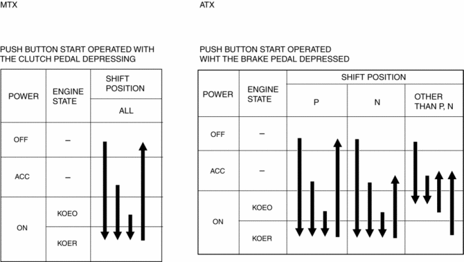
Vehicles with advanced keyless entry and push button start system
-
The power supply position can be switched as follows by operating the push button start with the advanced key in the vehicle. (Engine is off)
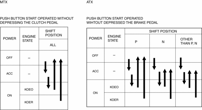
-
The engine can be started as follows by operating the push button start with the engine start conditions met. (Engine is running)
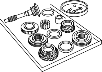
Removal of Parts
-
While correcting a problem, also try to determine its cause. Begin work only after first learning which parts and subassemblies must be removed and disassembled for replacement or repair. After removing the part, plug all holes and ports to prevent foreign material from entering.
Disassembly
-
If the disassembly procedure is complex, requiring many parts to be disassembled, all parts should be marked in a place that will not affect their performance or external appearance and identified so that reassembly can be performed easily and efficiently.
Inspection During Removal, Disassembly
-
When removed, each part should be carefully inspected for malfunction, deformation, damage and other problems.
Arrangement of Parts
-
All disassembled parts should be carefully arranged for reassembly.
-
Be sure to separate or otherwise identify the parts to be replaced from those that will be reused.
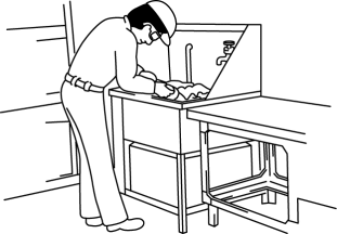
Cleaning of Parts
-
All parts to be reused should be carefully and thoroughly cleaned in the appropriate method.
WARNING:
-
Using compressed air can cause dirt and other particles to fly out causing injury to the eyes. Wear protective eye wear whenever using compressed air.
Reassembly
-
Standard values, such as torques and certain adjustments, must be strictly observed in the reassembly of all parts.
-
If removed, the following parts should be replaced with new ones:
-
Oil seals
-
Gaskets
-
O–rings
-
Lock washers
-
Cotter pins
-
Nylon nuts
-
Depending on location:
-
Sealant and gaskets, or both, should be applied to specified locations. When sealant is applied, parts should be installed before sealant hardens to prevent leakage.
-
Oil should be applied to the moving components of parts.
-
Specified oil or grease should be applied at the prescribed locations (such as oil seals) before reassembly.
Adjustment
-
Use suitable gauges and testers when making adjustments.
Rubber Parts and Tubing
-
Prevent gasoline or oil from getting on rubber parts or tubing.
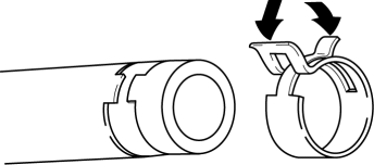
Hose Clamps
-
When reinstalling, position the hose clamp in the original location on the hose and squeeze the clamp lightly with large pliers to ensure a good fit.
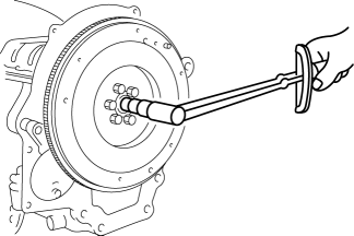
Torque Formulas
-
When using a torque wrench–SST
or equivalent combination, the written torque must be recalculated due to the extra length that the SST
or equivalent adds to the torque wrench. Recalculate the torque by using the following formulas. Choose the formula that applies to you.
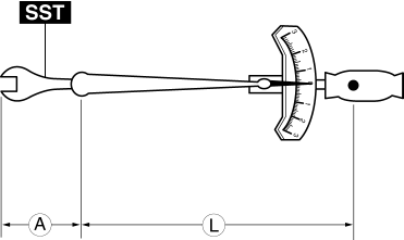
|
Torque Unit |
Formula |
|
N·m |
N·m × [L/(L+A)] |
|
kgf·m |
kgf·m × [L/(L+A)] |
|
kgf·cm |
kgf·cm × [L/(L+A)] |
|
ft·lbf |
ft·lbf × [L/(L+A)] |
|
in·lbf |
in·lbf × [L/(L+A)] |
A The length of the SST
past the torque wrench drive.
L The length of the torque wrench.
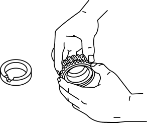
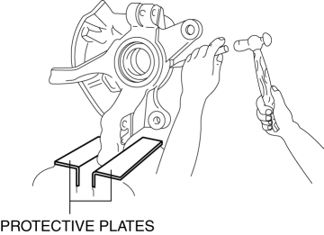
Vise
-
When using a vise, put protective plates in the jaws of the vise to prevent damage to parts.
Dynamometer
-
When inspecting and servicing the power train on the dynamometer or speed meter tester, pay attention to the following:
-
Place a fan, preferably a vehicle–speed proportional type, in front of the vehicle.
-
Make sure the vehicle is in a facility with an exhaust gas ventilation system.
-
Since the rear bumper might deform from the heat, cool the rear with a fan. (Surface of the bumper must be below 70°C {158°F}
.)
-
Keep the area around the vehicle uncluttered so that heat does not build up.
-
Watch the water temperature gauge and don’t overheat the engine.
-
Avoid added load to the engine and maintain normal driving conditions as much as possible.
NOTE:
-
When only the front or rear wheels are rotated on a chassis dynamometer or equivalent, the ABS/DSC HU/CM determines that there is a malfunction in the ABS and illuminates the following lights:
-
Vehicles with ABS
-
ABS warning light
-
Brake system warning light
-
Vehicles with DSC
-
ABS warning light
-
Brake system warning light
-
DSC indicator light
-
If the above lights are illuminated, dismount the vehicle from the chassis dynamometer and switch the ignition to LOCK. Then, switch the ignition to ON position, run the vehicle at 10 km/h or more and verify that the warning lights go out. In this case, a DTC will be stored in the memory. Clear the DTC from the memory by following the memory clearing procedure [ABS]/[DSC] in the on-board diagnostic system. (See ON-BOARD DIAGNOSIS [ABS].)(See ON-BOARD DIAGNOSIS [DYNAMIC STABILITY CONTROL (DSC)].)
-
If the engine cannot be stopped during an inspection, perform an emergency engine stop operation. (See Emergency Engine Stop Operation.)
Emergency Engine Stop Operation
-
While inspecting vehicles with ABS and DSC, if the engine cannot be stopped after a DTC related to the serviced part is indicated, perform an emergency engine stop operation using the following procedure.
1. Press the push button start continuously, or press and release the push button start repeatedly until the engine stops.
2. The engine stops (position is ACC).
3. Press the push button start to set the position to OFF.
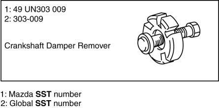
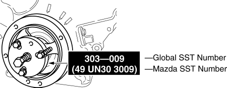
SST
-
Some global SST
or equivalent are used as SSTs
necessary for engine repair. Note that these SSTs
are marked with global SST
numbers.
-
Note that a global SST
number is written together with a corresponding Mazda SST
number as shown below.
Example (SST List)
Example (In text)
 Sae Standards
In accordance with new regulations, SAE (Society of Automotive Engineers)
standard names and abbreviations are now used in this manual. The table below
lists the names and abbreviations th ...
 Units
Units
Electric current
A (ampere)
Electric power
W (watt)
Electric resistance
ohm
Electric voltage
...
Other materials:
Afs (Adaptive Front Lighting System) Control Module Removal/Installation
NOTE:
Perform the auto leveling system initialization after newly replacing the
AFS control module to assure that the auto leveling system operates correctly.
1. Disconnect the negative battery cable..
2. Remove the following parts:
a. Passenger-side front scuff plate.
b. Pass ...
Canister Vent (Cv) Solenoid Valve Removal/Installation [Mzr 2.0, Mzr 2.5]
Except for Mexico
1. Remove the battery cover..
2. Disconnect the negative battery cable..
3. Remove in the order indicated in the table.
1
CV solenoid valve connector
2
Evaporative hose No.1
3
Evaporative hos ...
Body And Accessories
ABBREVIATIONS
ACC
Accessories
AUX
Auxiliary jack
CAN
Controller Area Network
DLC
Data Link Connector
GND
Ground
LH
Left Hand
...
