Mazda 3 Service Manual: Clutch Fluid Replacement/Air Bleeding [C66 M R]
CAUTION:
-
Do not allow clutch fluid get on a painted surface. Clutch fluid contains properties which can dissolve the paint. If clutch fluid gets on a painted surface, wash it off with water immediately and wipe the area off completely.
-
Do not mix different types of clutch fluid, otherwise the clutch may not operate normally.
-
Do not reuse old clutch fluid, otherwise the clutch may not operate normally.
NOTE:
-
A common reserve tank is used for the clutch system and brake system.
1. Remove the aerodynamic under cover No.2..
2. Drain the clutch fluid from bleeder screw.
3. Add new clutch fluid to the MAX mark of the reserve tank.
-
Clutch fluid
-
SAE J1703 or FMVSS116 DOT-3
4. Bleed the air from the clutch system.
CAUTION:
-
Keep the clutch fluid level in the reserve tank at 3/4 full or more during air bleeding.
a. Connect a vinyl tube to the bleeder screw.
b. Place the other end of the vinyl tube in a clear container, and fill clutch fluid in the container during air bleeding.
c. Working with two people, one loosens the bleeder screw.
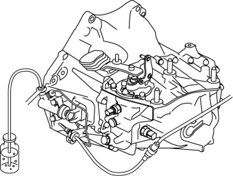
d. The other person depresses the clutch pedal to full stroke taking approx. 3 s or more, and then holding the pedal depressed.
e. After waiting approx. 5 s or more, tighten the bleeder screw.
f. Return the clutch pedal slowly taking 3 s or more while suppressing the spring force.
g. Wait approx. 5 s or more.
h. Continue to perform air bleeding (Steps (3) - (7)) until no air comes from the vinyl tube.
i. Fill the reserve tank to MAX mark with the clutch fluid.
-
Clutch fluid
-
SAE J1703 or FMVSS116 DOT-3
5. Install the aerodynamic under cover No.2..
 Clutch Fluid Leakage Inspection [C66 M R]
CAUTION:
Do not allow clutch fluid get on a painted surface. Clutch fluid contains
properties which can dissolve the paint. If clutch fluid gets on a painted surface,
wash it off with wa ...
 Clutch Master Cylinder Removal/Installation [C66 M R]
CAUTION:
Secure the steering wheel using tape or a cable to prevent the steering shaft
from rotating after disconnecting the steering shaft. If the steering wheel
rotates after the steer ...
Other materials:
Parking brake
The parking brake system in the Subaru Solterra can be engaged or
released either automatically or manually, providing flexibility and enhanced convenience
depending on driving conditions.
When operating in automatic mode, the Subaru Solterra intelligently manages the
parking brake, activat ...
Airflow Mode Main Link Removal/Installation
1. Set the air intake mode to FRESH.
2. Set the air mix mode to MAX COLD.
3. Disconnect the negative battery cable..
4. Remove the following parts:
a. Front doors.
b. Front scuff plate.
c. Front side trim.
d. Dashboard under cover.
e. Glove compartment.
f. Upper panel.
g. Shift l ...
Child restraint system fixed with a child restraint LATCH anchor
■ Child restraint LATCH anchors
The Subaru Solterra is equipped with dedicated LATCH anchors located in the outboard
positions of the rear seats. These anchors provide a secure and convenient method
for installing compatible child restraint systems without relying solely on seat
belts.
...
