
Mazda 3 Service Manual: Confirmation Step 3: Antenna System Simple Inspection [Radio]
-
Because the antenna system is equipped with a capacitor, the continuity cannot be checked. Therefore proceed the following simple inspection.
-
Turn the AM radio on.
-
Tune to the frequency that there is no broadcast and you will hear a buzzing sound.
-
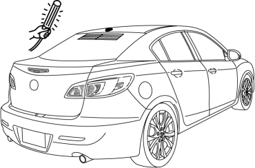
Turn a work light on and shake it around the antenna rod. (around 10—20 mm {0.40—0.78 in})
CAUTION:
-
Use a fluorescent light type for the inspection. Accurate diagnostic cannot be done with a different type of light.
-
-
If a whirring sound from the speaker synchronized to the work light movement is confirmed, the antenna system is normal.
 Coil Antenna Removal/Installation
1. Disconnect the negative battery cable..
2. Remove the column cover..
3. Remove the key cylinder..
4. Disconnect the coil antenna connector.
5. Remove the screw.
6. Detach the coil ante ...
 Entertainment Personalization Features Setting Procedure
Welcome Mode ON/OFF Setting
NOTE:
WELCOME mode is controlled by the instrument cluster. Refer to the instrument
cluster description.
1. Refer to INSTRUMENTATION/DRIVER INFO. PERSONAL ...
Other materials:
Cowl Panel Removal/Installation
1. Disconnect th negative battery cable..
2. Remove the windshield wiper arm and blade..
3. Remove the front fender molding..
4. Remove the cowl grille..
5. Remove the washer hose grommet from the cowl panel and disconnect the front
washer hose.
6. Remove the windshield wiper motor..
7 ...
Limitations to SRS Air Bag
In severe collisions such as those described previously in "SRS Air Bag
Deployment
Criteria", the applicable SRS air bag equipment will deploy. However, in some
accidents,
the equipment may not deploy depending on the type of collision and its
severity.
Limitations to front/near ...
High Mount Brake Light Removal/Installation
4SD
1. Disconnect the negative battery cable..
2. Remove the trunk lid trim..
3. Disconnect the connector.
4. Remove the nuts.
5. While pressing the tabs shown in the figure, pull the high-mount brake light
outward and remove it.
6. Remove the high-mount brake light.
7. Instal ...
