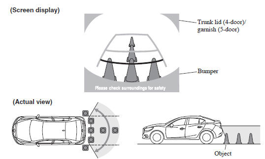
Mazda 3 Owners Manual: Displayable Range on the Screen
The images on the screen may be different from the actual conditions.
NOTE
- The displayable range varies depending on the vehicle and road conditions.
- The displayable range is limited. Objects under the bumper or around the bumper ends cannot be displayed.
- The distance appearing in the displayed image is different from the actual distance because the rear view parking camera is equipped with a specific lens.
- Some optionally installed vehicle accessories may be picked up by the camera. Do not install any optional parts that can interfere with the camera view, such as illuminating parts or parts made of reflective material.
- It may be difficult to see the display under the following conditions, however, it does not indicate a malfunction.
- In darkened areas.
- When the temperature around the lens is high/low.
- When the camera is wet such as on a rainy day or during periods of high humidity.
- When foreign material such as mud is stuck around the camera.
- When the camera lens reflects sunlight or headlight beams.
- Image display may be delayed if the temperature around the camera is low.
 Rear View Parking Camera Location
Switching to the Rear View Monitor Display
Shift the shift lever to R with the ignition switched ON to switch the
display to the rear view
monitor display.
NOTE
When the shift lever is shift ...
 Viewing the Display
Guide lines which indicate the width of the vehicle (yellow) are displayed on
the screen as a
reference to the approximate width of the vehicle in comparison to the width of
the parking
space yo ...
Other materials:
Recommended Tire Inflation Pressure
On the tire label you will find the recommended tire inflation pressure in
both kPa and
psi for the tires installed as original equipment on the vehicle. It is very
important that the
inflation pressure of the tires on your vehicle is maintained at the
recommended pressure.
You should che ...
Air Filter Removal/Installation [Skyactiv G 2.0]
1. Remove the fuel-filler pipe protector..
2. Remove in the order indicated in the table.
1
Evaporative hose
2
Air filter
3. Install in the reverse order of removal. ...
Cargo Compartment Light Removal/Installation
1. Disconnect the negative battery cable..
2. Insert a tape-wrapped fastener remover into the service hole and pry with
the screwdriver in the direction shown by the arrow to remove the cargo compartment
light.
3. Disconnect the connector.
4. Remove the cargo compartment light.
5 ...
