
Mazda 3 Service Manual: Headlight Leveling Actuator Inspection
NOTE:
-
Headlight leveling actuator are integrated with the front combination light.
-
For the actuator inspection of the headlight auto leveling system, perform the headlight leveling actuator operation inspection..
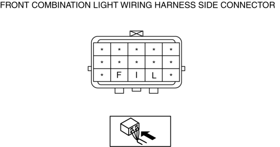
1. Measure the voltage at each terminal is as indicated in the Terminal Voltage Lists.
-
If the voltage is not as specified in the Terminal Voltage Lists, inspect the parts under “Inspection item (s)”.
-
If the system does not work properly even though the parts or related wiring harnesses do not have any malfunction, replace the front combination light.
Terminal Voltage List (Reference)
|
Terminal
|
Signal
|
Connection
|
Test condition
|
Voltage (V)/Continuity
|
Action
|
|
|
F |
Headlight leveling actuator signal |
Headlight leveling switch |
Light switch at HEAD position |
Switch position 0 position |
approx. 10.5 |
|
|
Switch position 1 position |
approx. 9.2 |
|||||
|
Switch position 2 position |
approx. 6.2 |
|||||
|
Switch position 3 position |
approx. 4.9 |
|||||
|
I |
Headlight leveling actuator power supply |
Headlight relay (LO) |
Light switch at HEAD position |
B+ |
|
|
|
Light switch at OFF position |
1.0 or less |
|||||
|
L |
GND |
Headlight leveling switch Body ground |
Under any condition |
1.0 or less |
|
|
 Headlight Bulb Removal/Installation
Halogen Type
Low-beam
1. Disconnect the negative battery cable..
2. Disconnect the connector.
3. Remove the cover.
4. Remove the adaptor.
5. Remove the headlight bulb (LO).
CAUTION ...
 High Mount Brake Light Bulb Removal/Installation
4SD
1. Disconnect the negative battery cable..
2. Remove the trunk lid trim..
3. Remove in the order indicated in the table.
1
Connector
2
...
Other materials:
Brake Hose (Front) Removal/Installation [Mzr 2.3 Disi Turbo]
1. Remove in the order indicated in the table.
2. Install in the reverse order of removal.
3. Add brake fluid, bleed the brakes, and inspect for leakage after the installation
has been completed..
1
Brake pipe
2
Clip
3
...
Key Reminder Switch Removal/Installation
1. Disconnect the negative battery cable. (See BATTERY REMOVAL/INSTALLATION [MZR
2.0, MZR 2.5].)(See BATTERY REMOVAL/INSTALLATION [MZR 2.3 DISI Turbo].)(See BATTERY
REMOVAL/INSTALLATION [SKYACTIV-G 2.0].)
2. Remove the column cover. (See COLUMN COVER REMOVAL/INSTALLATION.)
3. Disconnect the ...
Front Beltline Molding Removal/Installation
1. Fully open the front door glass.
2. Disconnect the negative battery cable..
3. Remove the inner garnish..
4. Remove the front door trim..
5. Remove the power outer mirror..
6. Remove clip A using a fastener remover and pull the front beltline molding
in the direction of the arrow (1) ...
