Mazda 3 Service Manual: Hydraulic Variable Valve Timing Actuator Inspection [Skyactiv G 2.0]
WARNING:
-
A hot engine can cause severe burns. Turn off the engine and wait until it is cool before servicing.
CAUTION:
-
Do not disassemble the hydraulic variable valve timing actuator because it is a precision unit.
1. Remove the battery cover..
2. Disconnect the negative battery cable..
3. Remove the plug hole plate..
4. Remove the ignition coil/ion sensors..
5. Remove the cylinder head cover..
6. Verify that the notch of the rotor and projection of the cover on the hydraulic variable valve timing actuator are aligned and fitted.
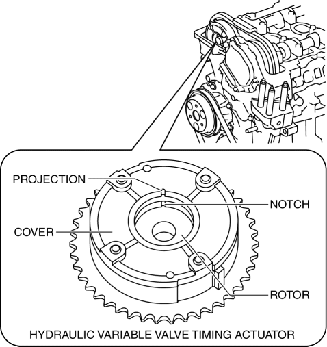
-
If the notch of the rotor and projection of the cover are not aligned, rotate the crankshaft in the direction the engine rotates two turns and verify that they are aligned.
-
If the notch of the rotor and projection of the cover are still not aligned, replace the hydraulic variable valve timing actuator..
-
If, when turning the crankshaft, there is a hitting noise from the hydraulic variable valve timing actuator each time before the cam reaches its maximum lift, it means that the actuator is not secured. Replace the hydraulic variable valve timing actuator..
7. Install in the reverse order of removal.
 Variable Valve Timing Actuator Removal/Installation [Mzr 2.3 Disi Turbo]
WARNING:
Fuel vapor is hazardous. It can very easily ignite, causing serious injury
and damage. Always keep sparks and flames away from fuel.
Fuel line spills and leakage are danger ...

Other materials:
Joint Shaft Removal/Installation [Mzr 2.0, Mzr 2.3 Disi Turbo, Mzr 2.5]
CAUTION:
Performing the following procedures without first removing the ABS wheel-speed
sensor may possibly cause an open circuit in the wiring harness if it is pulled
by mistake. Before performing the following procedures, remove the ABS wheel-speed
sensor connector (axle side) and ...
Fog light switch
In challenging weather conditions such as heavy rain, dense fog,
or mist, the Subaru Solterra allows you to activate the front fog lights to significantly
improve forward visibility and enhance overall driving safety.
Turning on the fog lights
*1
or
*2
Turns the front fog l ...
Bright-Metal Maintenance
Use tar remover to remove road tar and
insects. Never do this with a knife or
similar tool.
To prevent corrosion on brightmetal
surfaces, apply wax or chrome
preservative and rub it to a high luster.
During cold weather or in coastal areas,
cover bright-metal parts with a coating
...
