Mazda 3 Service Manual: Precaution
Intermittent Concern Troubleshooting
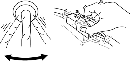
Vibration method
-
If malfunction occurs or becomes worse while driving on a rough road or when the engine is vibrating, perform the steps below.
NOTE:
-
There are several reasons why vehicle or engine vibration could cause an electrical malfunction. Some of the things to check for are:
-
Connectors not fully seated
-
Wire harnesses not having full play
-
Wires laying across brackets or moving parts
-
Wires routed too close to hot parts
-
An improperly routed, improperly clamped, or loose harness can cause wiring to become pinched between parts.
-
The connector joints, points of vibration, and places where wire harnesses pass through the firewall, body panels and other panels are the major areas to be checked.
Inspection method for switch and/or sensor connectors or wires
1. Connect the M-MDS to the DLC-2.
2. Switch the ignition to ON (engine off).
NOTE:
-
If engine starts and runs, perform the following steps at idle.
3. Access the PIDs for the switch you are inspecting.
4. Turn switch on manually.
5. Shake each connector or wire harness a bit vertically and horizontally while monitoring the PID.

-
If the PID value is unstable, check for poor connection.
Inspection method for sensors
1. Connect the M-MDS to the DLC-2.
2. Switch the ignition to ON (engine off).
NOTE:
-
If engine starts and runs, perform the following steps at idle.
3. Access the PIDs for the switch you are inspecting.
4. Vibrate the sensor slightly with your finger.
-
If the PID value is unstable or malfunction occurs, check for poor connection and/or poorly mounted sensor.
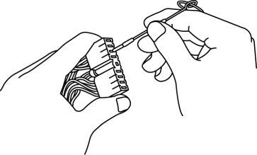
Connector terminal check method
1. Check the connection condition of each female terminal.
2. Insert male terminal; fit the female terminal side to female terminal and check to see whether the malfunction is in the female terminal or not.

 General Procedures (Suspension)
Wheel and Tire Installation
1. When installing the wheels and tires, tighten the wheel nuts in a criss-cross
pattern to the following tightening torque.
Tightening torque
88—118 N·m { ...
 Rear Trailing Link Removal/Installation
CAUTION:
Performing the following procedures without first removing the ABS wheel-speed
sensor may possibly cause an open circuit in the wiring harness if it is pulled
by mistake. Before ...
Other materials:
Side Turn Light Inspection
Side turn light illumination inspection
1. Disconnect the negative battery cable..
2. Remove the outer mirror glass..
3. Remove the outer mirror garnish..
4. Remove the side turn light..
5. Connect the battery voltage as shown in the figure.
If the side turn light does illuminat ...
Brake/Taillight Bulb Removal/Installation
4SD
1. Disconnect the negative battery cable..
2. Remove the following parts:
a. Trunk mat.
b. Trunk board.
c. Trunk end trim.
3. Partially peel back the trunk side trim..
4. Remove in the order indicated in the table.
1
Connector
2
...
Seat Belt Warning Beep
If the driver's seat belt is not fastened
when the ignition is switched ON, a beep
sound will be heard for about 6 seconds. If
the driver or the front passenger's seat belt
is not fastened and the vehicle is driven
at a speed faster than about 20 km/h (12
mph), a beep sound will be heard again ...
