
Mazda 3 Service Manual: Relay Block Inspection [With Advanced Keyless Entry And Push Button Start System]
1. Disconnect the negative battery cable..
2. Remove the following parts:
a. Driver-side front scuff plate.
b. Driver-side front side trim.
c. Hood release lever.
d. Upper panel.
e. Shift knob (MTX)(See MANUAL TRANSAXLE SHIFT MECHANISM REMOVAL/INSTALLATION [G66M-R].)(See MANUAL TRANSAXLE SHIFT MECHANISM REMOVAL/INSTALLATION [A26M-R].)
f. Selector lever knob (ATX)(See AUTOMATIC TRANSAXLE SHIFT MECHANISM REMOVAL/INSTALLATION.)
g. Shift panel.
h. Side wall.
i. Console.
j. Lower panel.
k. Knee bolster.
3. Remove the relay block..
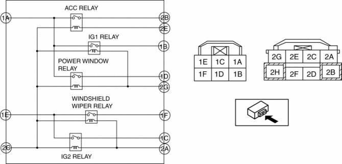
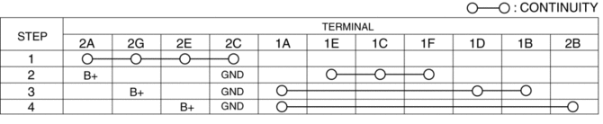
4. Verify that the continuity is as indicated in the table.
-
If not as indicated in the table, replace the relay block.
 Main Fuse Removal/Installation
1. Disconnect the negative battery cable..
2. Remove nuts A and B shown in the figure.
3. Remove the main fuse.
4. Install in the reverse order of removal. ...
 Relay Block Removal/Installation [With Advanced Keyless Entry And Push Button
Start System]
Relay Block Removal/Installation [With Advanced Keyless Entry And Push Button
Start System]
1. Disconnect the negative battery cable..
2. Remove the following parts:
a. Driver-side front scuff plate.
b. Driver-side front side trim.
c. Hood release lever.
d. Upper panel.
e. Shift ...
Other materials:
General Procedures (Suspension)
Wheel and Tire Installation
1. When installing the wheels and tires, tighten the wheel nuts in a criss-cross
pattern to the following tightening torque.
Tightening torque
88—118 N·m {9.0—12 kgf·m, 65—87 ft·lbf}
Suspension Links Removal/Installation
1. For the joint ...
Operational Range
WARNING
Always take all children and pets with
you or leave a responsible person with
them:
Leaving a child or a pet unattended in
a parked vehicle is dangerous. In hot
weather, temperatures inside a vehicle
can become high enough to cause
brain damage or even death.
...
Filament Inspection
1. Turn the ignition switch to the ON position.
2. Turn the rear window defroster switch on.
CAUTION:
Directly touching the rear window defroster filament with the lead of the
tester could damage it. Wrap aluminum foil around the end of the lead and inspect
the filament by touc ...
