Mazda 3 Owners Manual: Speedometer
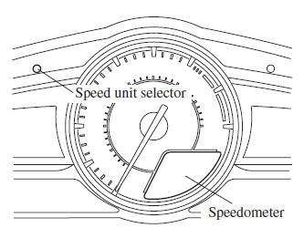
The speedometer indicates the speed of the vehicle.
Speed Unit Selector (Type A Instrument Cluster)
In some countries, you may have to change the speed units between km/h and mph.
Press the speed unit selector for 1.5 seconds or more.
The speed units for the speedometer will change between km/h and mph.
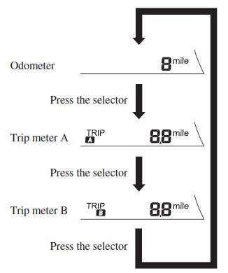
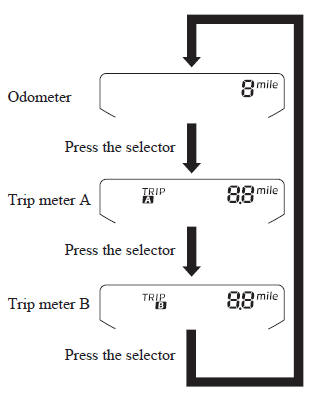
Odometer, Trip Meter and Trip Meter Selector
The display mode can be changed from odometer to trip meter A to trip meter B and then back to odometer by pressing the selector while one of them is displayed.
The selected mode will be displayed.
Type A/Type B
Type C
NOTE When the ignition is switched to ACC or off, the odometer or trip meters cannot be displayed, however, pressing the selector can inadvertently switch the trip meters or reset them during an approximate tenminute period in the following cases:
- After the ignition is switched to off from ON.
- After the driver's door is opened.
Odometer
The odometer records the total distance the vehicle has been driven.
Trip meter
The trip meter can record the total distance of two trips. One is recorded in trip meter A, and the other is recorded in trip meter B.
For instance, trip meter A can record the distance from the point of origin, and trip meter B can record the distance from where the fuel tank is filled.
When trip meter A is selected, pressing the selector again within one second will change to trip meter B mode.
When trip meter A is selected, TRIP A will be displayed. When trip meter B is selected, TRIP B will be displayed.
The trip meter records the total distance the vehicle is driven until the meter is again reset. Return it to “0.0” by depressing and holding the selector for one second or more. Use this meter to measure trip distances and to compute fuel consumption.
NOTE
- (Vehicles with type B audio)
If the fuel economy data is reset using
the fuel economy monitor, or trip A
is reset using the trip meter when the
function which synchronizes the fuel
economy monitor and the trip meter is
on, the fuel economy data and trip A are
reset simultaneously.
Refer to Fuel Economy Monitor on .
- Only the trip meters record tenths of kilometers (miles).
- The trip record will be erased when:
- The power supply is interrupted (blown fuse or the battery is disconnected).
- The vehicle is driven over 9999.9 km (mile).
 Meters and Gauges
Speedometer
Odometer, Trip Meter and Trip Meter Selector
Tachometer
Fuel Gauge
Dashboard Illumination.
Outside Temperature Display .
Cruise Control Set Vehicle Speed Display
Acti ...
 Tachometer
The tachometer shows engine speed in
thousands of revolutions per minute (rpm).
CAUTION
Do not run the engine with the
tachometer needle in the RED ZONE.
This may cause severe engine ...
Other materials:
Customer Assistance (U.S.A.)
Your complete and permanent satisfaction is our business. We are here to
serve you. All
Authorized Mazda Dealers have the knowledge and the tools to keep your Mazda
vehicle in
top condition.
If you have any questions or recommendations for improvement regarding the
service of
your Mazda ...
Pressure Sensor Removal/Installation [Two Step Deployment Control System]
1. Switch the ignition to off.
2. Disconnect the negative battery cable and wait for 1 min or more..
3. Remove the inner garnish..
4. Remove the front door trim..
5. Remove the bolts.
6. Remove the pressure sensor.
7. Disconnect the connector from the pressure sensor by pressing the ...
Theft Deterrent System Clearing Freeze Frame Data
1. Connect the M-MDS (IDS) to the DLC–2.
2. After the vehicle is identified, select the following items from the initialization
screen of the IDS.
Select “Body”.
Select "Burglar Service Functions".
3. Then, select the following item from the screen menu. ...
