Mazda 3 Service Manual: Vehicle Speed Sensor (VSS) Inspection [FS5 A EL]
On-Vehicle Inspection
1. Inspect the power supply circuit for the VSS.
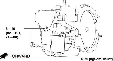
a. Remove the insulator from the transaxle.

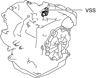
b. Disconnect the VSS connector.

c. Switch the ignition to ON (engine off).
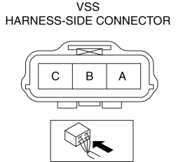
d. Measure the voltage at VSS connector terminal A (harness-side).

-
If there is any malfunction, repair wiring harness between VSS and AT main relay.
-
VSS specification
-
B+
e. Switch the ignition to off.
f. Connect the VSS connector.
2. Inspect the GND circuit for the VSS.
a. Switch the ignition to off.
b. Measure the voltage at VSS connector terminal C (harness-side).

-
If there is any malfunction, repair wiring harness between VSS and GND.
-
VSS specification
-
Below 1.0 V
3. Inspect the signal circuit for the VSS.
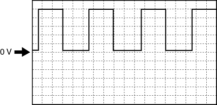
a. Connect the oscilloscope to the following TCM connector terminals and set it as below.
-
(+) lead: TCM terminal Z
-
(-) lead: battery negative terminal
-
Oscilloscope setting: 1 V/DIV (Y), 2 ms/DIV (X), DC range
b. Start the engine.
c. Measure the wave form when the following conditions are met.
-
Gear position: 3GR
-
Vehicle speed: 30 km/h {19 mph}

-
If there is any malfunction, replace the VSS..
 Knock Sensor (Ks) Removal/Installation [Mzr 2.0, Mzr 2.5]
1. Remove the battery cover..
2. Disconnect the negative battery cable..
3. Remove the plug hole plate..
4. Remove the intake manifold..
5. Disconnect the KS connector.
6. Remove the KS.
...
 Vehicle Speed Sensor (VSS) Removal/Installation [FS5 A EL]
CAUTION:
If foreign materials are stuck to the sensor, disturbance by magnetic flux
can cause sensor output to be abnormal and thereby negatively affect control.
Make sure that foreign m ...
Other materials:
Shift-Lock System
The shift-lock system prevents shifting out
of P unless the brake pedal is depressed.
To shift from P:
Depress and hold the brake pedal.
Start the engine.
Press and hold the lock-release button.
Move the selector lever.
NOTE
When the ignition is switched to ACC or
the ignition ...
Column Cover Removal/Installation
1. Pull down the steering wheel.
2. Pull the upper column cover in the direction of the arrow in the order of
(1) and (2), then remove the upper column cover while detaching the hooks and pins.
3. Pull up the steering wheel.
4. Remove the ignition key illumination..
5. Remove the scre ...
Liftgate Side Trim Removal/Installation
1. Remove the liftgate upper trim..
2. Pull the point A of the strap hanger as shown in the figure.
3. Remove the strap hanger.
4. Remove the fastener.
5. Pull the liftgate side trim in the direction of arrow then remove clip A.
6. Detach tab B and C while pulling the liftgate sid ...
