Mazda 3 Service Manual: Wheel Unit ID Registration
NOTE:
-
After the wheel unit replacement, registration of the wheel unit identification codes must be performed.
-
ID registration can be done using the M-MDS, or not using the M-MDS.
Using M-MDS
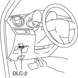
1. Connect the M-MDS to DLC-2.

2. After the vehicle is identified, select the following items from the initialization screen of the M-MDS.
-
This function is available for only the IDS (laptop PC).
-
Select the “Body”.
-
Select the “TPMS Functions”.
-
Select the “Wheel Unit ID Registration”.
3. Select an item from the screen menu.
-
Wheel unit ID registration: WU ID Registration
-
Monitoring wheel unit ID: Monitor WU ID Registration
4. Leave the vehicle with the ignition to off for 15 min or more
.
5. Switch the ignition to ON (engine ON).
6. Verify that the TPMS warning light turns on and off in 0.5 s
cycles repeatedly.
7. Drive the vehicle at a speed of 25 km/h {15.5 mph} or more
for 10 min
to implement the wheel unit ID registration.
NOTE:
-
If the ID registration is not completed even after driving the vehicle for 10 min
or more at a speed of 25 km/h {15.5 mph} or more
, the TPMS warning light flashes.
8. Verify that the TPMS warning light turns off.
NOTE:
-
If the wheel unit ID registration cannot be performed after driving 10 min
or more, refer to the symptom troubleshooting procedure.
Without Using M-MDS
1. Switch the ignition to the ON, then switch it to off.
2. Leave the vehicle with the engine off for 15 min or more
.
3. Drive the vehicle at a speed of 25 km/h {15.5 mph} or more
for 10 min or more
.
4. After driving for 10 min
, verify that the TPMS warning light does not flash and is not illuminated.
 Wheel Balance Adjustment
CAUTION:
Adjust the outer wheel balance first, then the inner wheel balance.
Be careful not to scratch the wheels.
Adhesive-type Balance Weight (Outer)
1. Remove the old balance ...
 Wheel Unit Removal/Installation
1. Remove in the order indicated in the table.
2. Install in the reverse order of removal.
3. Install the valve core and valve cap, put air into the tire.
CAUTION:
A TPMS wheel unit has ...
Other materials:
Instrument Cluster Removal/Installation
CAUTION:
When replacing the instrument cluster, the configuration procedure must be
performed before removing the instrument cluster. Replacing the instrument cluster
without performing the configuration procedure will result in system malfunction.
1. Perform the instrument clust ...
Rear Buckle Removal/Installation
Rear Buckle (RH) and Rear Buckle (Center)
1. Remove the rear seat cushion..
2. Remove the bolt.
3. Remove the rear buckle (RH) and rear buckle (center).
4. Install in the reverse order of removal.
Rear Buckle (LH)
1. When removing or installing the rear buckle (LH), refer to the rear ...
Event Data Recorder
This vehicle is equipped with an event data recorder (EDR). The main purpose
of an EDR
is to record, in certain crash or near crash-like situations, such as an air bag
deployment
or hitting a road obstacle, data that will assist in understanding how a
vehicle’s systems
performed. The EDR is ...
