Mazda 3 Service Manual: ABS HU/CM Removal/Installation
WARNING:
-
If the ABS HU/CM configuration is not completed, it could result in an unexpected accident due to the ABS being inoperative. If the ABS HU/CM or ABS CM is replaced, always use the automatic configuration function so that the ABS operation conditions are correct.
CAUTION:
-
The internal parts of the ABS HU/CM could be damaged if dropped. Be careful not to drop the ABS HU/CM. Replace the ABS HU/CM if it is subjected to an impact.
-
Do not separate the ABS HU and ABS CM unless replacing them, otherwise the ABS HU/CM may not function properly. When replacing them with new ones, always perform procedures according to the instructions included with the new parts.
NOTE:
-
When the ignition is switched to ON or the engine is started after the ABS HU/CM or ABS CM has been replaced, the ABS CM reads data from the instrument cluster via CAN communication to perform automatic configuration.
1. Remove the battery and battery tray..
2. Remove in the order indicated in the table.
3. Install in the reverse order of removal.
4. Switch the ignition to ON or start the engine, and maintain this condition for approx. 30 s
to allow the ABS HU/CM automatic configuration to be performed.
5. Clear the DTCs from the memory..
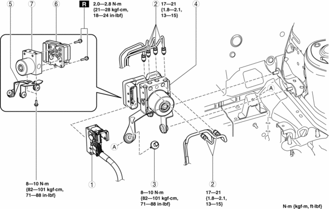
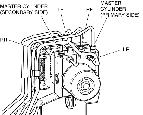
|
1 |
Connector (See Connector Removal Note.) (See Connector Installation Note.) |
|
2 |
Brake pipe (See Brake Pipe Removal Note.) (See Brake Pipe Installation Note.) |
|
3 |
Bolt |
|
4 |
ABS HU/CM component, bracket (See ABS HU/CM Component, Bracket Removal Note.) |
|
5 |
Bracket |
|
6 |
ABS CM |
|
7 |
ABS HU |
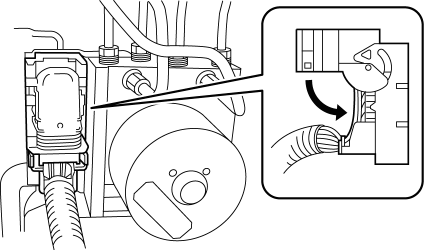
Connector Removal Note
1. Pull the connector cover up in the direction of the arrow while pressing the tab of the connector cover.
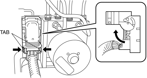
2. Pull the connector toward the vehicle front and remove it.
Brake Pipe Removal Note
1. Place an alignment mark on the brake pipe and ABS HU/CM.
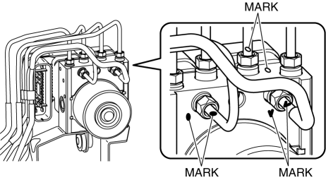
2. Apply protective tape to the connector to prevent brake fluid from entering.
3. Disconnect the brake pipe.
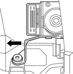
ABS HU/CM Component, Bracket Removal Note
1. As shown in the figure, move the bracket in the direction of the arrow and remove the ABS HU/CM component and bracket from the body.
Brake Pipe Installation Note
1. Align the marks made before removal and install the brake pipe to the ABS HU/CM referring to the figure.
Connector Installation Note
1. After connecting the connector, verify that the connector cover is completely pushed in.
 ABS HU/CM Inspection
1. Disconnect the ABS HU/CM connector..
2. Connect the negative battery cable..
3. Attach the tester lead to the ABS HU/CM wiring harness-side connector and
inspect the voltage, continuity, or r ...
 Front ABS Wheel Speed Sensor Inspection
Sensor Output Value Inspection
CAUTION:
Resistance inspection using other testers may cause damage to the ABS wheel-speed
sensor internal circuit. Be sure to use the M-MDS to inspect the A ...
Other materials:
Battery Inspection [Mzr 2.3 Disi Turbo]
WARNING:
Since battery acid is toxic, be careful when handling the battery.
Since battery acid is highly corrosive, be careful not to allow it to contact
clothing or the vehicle.
In case battery acid contacts skin, eyes, or clothing, flush it immediately
with running wa ...
Head Restraints
Your vehicle is equipped with head
restraints on all outboard seats and the
rear center seat * . The head restraints
are intended to help protect you and the
passengers from neck injury.
WARNING
Always drive with the head restraints
installed when seats are being used and
make s ...
Automatic Transaxle Fluid (ATF) Adjustment [Fw6 A EL]
CAUTION:
Only adjust the ATF level when the ATF temperature is 45—55 °C {113—131 °F}.
If the ATF level is incorrect, it could damage the transaxle.
Do not add ATF over the specification. Otherwise, the transaxle performance
could be reduced and ATF could leak.
1. Re ...
