
Mazda 3 Service Manual: Antenna Feeder No.4 Inspection
1. Disconnect the negative battery cable..
2. Remove the following parts:
a. Upper column cover.
b. Instrument cluster.
c. Center panel.
d. Audio unit (Vehicles with audio unit).
e. Center cover.
f. Dashboard upper panel.
g. Front scuff plate (RH).
h. Front side trim (RH).
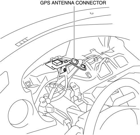
3. Disconnect the GPS antenna connector.
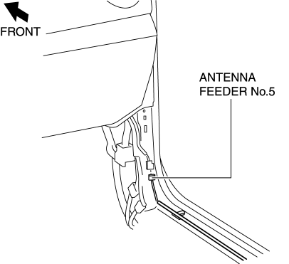
4. Disconnect the antenna feeder No.5.
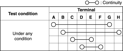
5. Verify that the continuity between antenna feeder No.4 terminals is as indicated in the table.
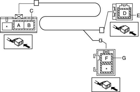
-
If not as indicated in the table, replace antenna feeder No.4.
 Antenna Feeder No.3 Removal/Installation
4SD (With Audio Unit (With Display))
1. Disconnect the negative battery cable..
2. Remove the rain sensor cover. (Vehicles with auto light/wiper system).
3. Disconnect the rain sensor connector. ...
 Antenna Feeder No.4 Removal/Installation
Removal
NOTE:
The antenna feeder No.4 is integrated with the dashboard wiring harness.
1. Refer to DASHBOARD DISASSEMBLY/ASSEMBLY.
Installation
CAUTION:
If the antenna feeder ...
Other materials:
Rear Door Trim Removal/Installation
1. Disconnect the negative battery cable..
2. Move the hook in the direction of arrow shown in the figure using a tape-lapped
flathead screwdriver and detach it from the rear door trim.
CAUTION:
Affix protective tape to the rear door trim and assist handle cover to prevent
damag ...
How to use AC charging
This section provides a detailed step-by-step guide for charging
the traction battery of the Subaru Solterra using an AC charging cable, ensuring
safe and efficient operation in everyday conditions.
When using an external AC charger with the Subaru Solterra, always review and
follow the spe ...
Headliner Removal/Installation
1. Shift to the D (ATX) or 4th gear (MTX) position. (4SD)
2. Disconnect the negative battery cable..
3. Remove the rain sensor cover. (Vehicles with auto light/wiper system).
4. Disconnect the rain sensor connector. (Vehicles with auto light/wiper system)
5. Partially peel back the seaming ...
