Mazda 3 Owners Manual: Auto Lock/Unlock Function
| WARNING Do not pull the inner handle on a front door: Pulling the inner handle on a front door while the vehicle is moving is dangerous. Passengers can fall out of the vehicle if the door opens accidentally , which could result in death or serious injury. |
- When the vehicle speed exceeds 20 km/h (12 mph), all doors and the liftgate lock automatically.
- When the ignition is switched off, all doors and the liftgate unlock automatically.
These functions can also be disabled so that they do not operate.
Auto lock/unlock function setting change using door-lock switch
The doors and the liftgate can be set to lock or unlock automatically by selecting any one of the functions from the following table and using the driver's doorlock switch on the interior door panel.
NOTE
- Function number 3 is the factory setting for your vehicle.
- There are only a total of five auto lock/ unlock settings available for automatic transaxle vehicles, and three for manual transaxle vehicles. Be sure to press the unlock side of the driver's door-lock switch the correct number of times according to the selected function number. If the switch is mistakenly pressed six times on an automatic transaxle vehicle or four times on a manual transaxle, the procedure will be cancelled. If this occurs, start the procedure from the beginning.
|
Function number |
Function *1 |
| 1 | The auto door-lock function is disabled. |
| 2 | All the doors and the liftgate lock automatically when the vehicle speed is about 20 km/h (12 mph) or more. |
| 3 | All the doors and the liftgate lock
automatically when the vehicle speed
is about 20 km/h (12 mph) or more. All the doors and the liftgate unlock when the ignition is switched from ON to Off. |
| 4 | (Automatic transaxle vehicles only) When the ignition is switched ON and the shift lever is shifted from park (P) to any other gear position, all the doors and the liftgate lock automatically. |
| 5 | (Automatic transaxle vehicles only)
When the ignition is switched ON
and the shift lever is shifted from
park (P) to any other gear position,
all the doors and the liftgate lock
automatically. When the shift lever is shifted to park (P) while the ignition is switched ON, all the doors and the liftgate unlock automatically. |
*1 Other settings for the auto door lock function are available at an Authorized Mazda Dealer. For details consult an Authorized Mazda Dealer. Refer to Personalization Features on .
Settings can be changed using the following procedure.
- Safely park the vehicle. All doors must remain closed.
- Switch the ignition ON.
- Press and hold the lock side of the driver's door-lock switch within 20 seconds of switching the ignition ON, and make sure a beep sound is heard about eight seconds afterwards.
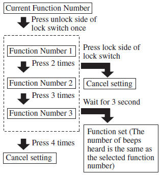
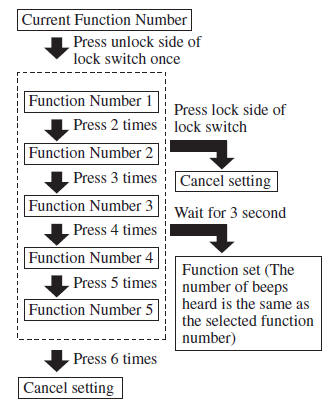
- Refer to the auto lock/unlock function setting table, determine the function number for the desired setting. Press the unlock side of the driver's door-lock switch the same number of times as the selected function number (Ex. If you select function 2, press the unlock side of the switch only 2 times).
- Three seconds after the function setting has been changed, a beep sound will beep in the amount of the selected function number. (Ex. Function number 3 = 3 beep sounds)
(Manual transaxle vehicles)
(Automatic transaxle vehicles)
NOTE
- The doors cannot be locked or unlocked while the setting function is being performed.
- The procedure can be cancelled by pressing the lock side of the driver's door-lock switch.
 Locking, Unlocking
Locking, Unlocking with
Transmitter
All doors and the liftgate can be locked/ unlocked by operating the keyless
entry system transmitter, refer to Keyless Entry System .
Locking, Unlocking with D ...
 Locking, Unlocking with Door-
Lock Knob
Locking, Unlocking with Door-
Lock Knob
Operation from inside
To lock any door from the inside, press the
door-lock knob.
To unlock, pull it outward.
This does not operate the other door locks.
NOTE
The red indication can be s ...
Other materials:
Driver Side Air Bag Module Removal/Installation [Two Step Deployment Control
System]
WARNING:
Handling the air bag module improperly can accidentally deploy the air bag
module, which may seriously injure you. Read the air bag system service warnings
and cautions before handling the air bag module..
Due to the adoption of 2-step deployment control in the driver- ...
Wheels
For the Subaru Solterra, any wheel that shows signs of bending, cracking,
or severe corrosion must be replaced immediately. Continuing to use a damaged wheel
can lead to tire separation or a serious loss of vehicle control while driving.
Wheel selection
When selecting replacement wheels for th ...
Information on Passenger Vehicle Tires
Please refer to the sample below.
TIN: U.S. DOT tire identification number
Passenger car tire
Nominal width of tire in millimeters
Ratio of height to width (aspect ratio)
Radial
Run-flat tire
Rim diameter code
Load index & speed symbol
Severe snow conditions
Tire ply co ...
