
Mazda 3 Service Manual: Combination Switch Disassembly/Assembly
CAUTION:
-
Handling the air bag module improperly can accidentally deploy the air bag module, which may seriously injure you. Read the air bag system service warnings and cautions before handling the air bag module..
1. Switch the ignition to off.
2. Disconnect the negative battery cable and wait for 1 min or more.
.
3. Remove the following parts:
a. Driver-side air bag module.
b. Steering wheel.
c. Column cover.
d. Clock spring.
e. Combination switch.
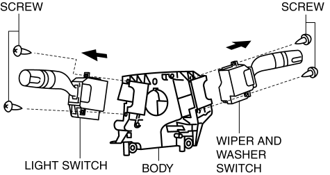
4. Remove the screws shown in the figures, then pull the light switch, and the wiper and washer switch in the direction of the arrow respectively to remove them.
5. Assemble in the reverse order of disassembly.
 Back Up Light Switch Removal/Installation [G66 M R]
1. Remove the battery cover..
2. Disconnect the negative battery cable.
3. Remove the battery component. (ex: battery, battery tray and PCM component).
4. Remove the aerodynamic under cover No. ...
 Combination Switch Removal/Installation
CAUTION:
Handling the air bag module improperly can accidentally deploy the air bag
module, which may seriously injure you. Read the air bag system service warnings
and cautions before h ...
Other materials:
Neutral Switch Removal/Installation [C66 M R]
1. Remove the battery cover..
2. Disconnect the negative battery cable..
3. Remove the aerodynamic under cover No.2..
4. Install in the reverse order of removal.
5. Remove in the order indicated in the table.
6. Install in the reverse order of removal.
1
Neutr ...
Oil Control Valve (OCV) Removal/Installation [Mzr 2.3 Disi Turbo]
1. Remove the battery cover..
2. Disconnect the negative battery cable..
3. Remove the charge air cooler..
4. Remove the ignition coils..
5. Disconnect the ventilation hose from the cylinder head cover..
6. Remove the cylinder head cover..
7. Remove in the order indicated in the table.
...
Power Brake Unit Removal/Installation [Mzr 2.0, Skyactiv G 2.0, Mzr 2.5]
CAUTION:
Once the brake switch clearance has automatically been adjusted, it cannot
be adjusted again. Therefore, replace the switch with a new one when replacing
the power brake unit or performing any procedure that changes the pedal stroke.
Secure the steering wheel using tap ...
