Mazda 3 Owners Manual: Commander switch operation
NOTE For safety reasons, some operations are disabled while the vehicle is being driven.
Volume dial operation
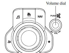
Press the volume dial to switch the audio MUTE on and off.
Turn the volume dial to adjust the volume. The volume increases by turning the dial clockwise, and decreases by turning it counterclockwise.
Switches around commander knob
The following operations can be done by pressing the switches around the commander knob.
 : Displays the home screen.
 : Displays the Entertainment screen.
 : Displays the Navigation screen
(Only navigation-equipped vehicles). For operation
of the Navigation screen, refer to the navigation system manual. If the SD card
for the
navigation system is not inserted, the compass indicating the direction in which
the vehicle
is moving is displayed.
 : Displays the Favorites screen.
Long-press to store particular items in Favorites. (Radio,
phonebook and destination of the navigation system can be programmed.)
 : Returns to previous screen.
Commander knob operation
(Selection of icons on screen)
- Tilt or turn the commander knob and move the cursor to the desired icon.
- Press the commander knob and select the icon.
NOTE Long-press operation of the commander knob is also possible for some functions.
Touch panel operation
| CAUTION Do not press the screen strongly or press it with a sharp-pointed object. Otherwise, the screen could be damaged. |
NOTE For safety reasons, operation of the center display is disabled while the vehicle is being driven. However, items not displayed in gray can be operated using the commander switch while the vehicle is being driven.
 Audio Set (Type B)
NOTE
The explanation of functions described in this manual may differ from the actual
operation, and the shapes of screens and buttons and the letters and characters
displayed
may also differ fro ...
 Basic Operation Method
TOUCH & TAP
Touch or tap on the item indicated on the screen.
The operation is launched and the next item is displayed.
SLIDE
Touch the setting item displaying a slider bar.
Tou ...
Other materials:
Receiving and Replying to
Messages (available only with
Email/SMS compatible phones)
SMS (Short Message Service) messages,
and E-mail received by connected devices
can be downloaded, displayed, and played
(read by the system).
Additionally, replies can also be made
to calls and messages in the received
messages.
Downloading messages
Up to 20 new messages can be
downloaded ...
Down Switch Inspection [Fw6 A EL]
Continuity Inspection
NOTE:
The down switch is built into the selector lever component.
1. Remove the battery cover..
2. Disconnect the negative battery cable..
3. Remove the console..
4. Disconnect the selector lever component connector.
5. Verify that the continuity betw ...
Camshaft Position (CMP) Sensor Removal/Installation [Mzr 2.0, Mzr 2.5]
CAUTION:
When replacing the CMP sensor, make sure there is no foreign material on
it such as metal shavings. If it is installed with foreign material, the sensor
output signal will malfunction resulting from fluctuation in magnetic flux and
cause a deterioration in engine control.
...
