
Mazda 3 Service Manual: Confirmation Step 3: Antenna System Simple Inspection [Radio]
-
Because the antenna system is equipped with a capacitor, the continuity cannot be checked. Therefore proceed the following simple inspection.
-
Turn the AM radio on.
-
Tune to the frequency that there is no broadcast and you will hear a buzzing sound.
-
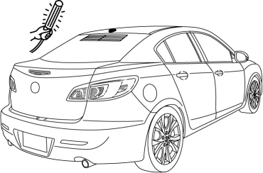
Turn a work light on and shake it around the antenna rod. (around 10—20 mm {0.40—0.78 in})
CAUTION:
-
Use a fluorescent light type for the inspection. Accurate diagnostic cannot be done with a different type of light.
-
-
If a whirring sound from the speaker synchronized to the work light movement is confirmed, the antenna system is normal.
 Coil Antenna Removal/Installation
1. Disconnect the negative battery cable..
2. Remove the column cover..
3. Remove the key cylinder..
4. Disconnect the coil antenna connector.
5. Remove the screw.
6. Detach the coil ante ...
 Entertainment Personalization Features Setting Procedure
Welcome Mode ON/OFF Setting
NOTE:
WELCOME mode is controlled by the instrument cluster. Refer to the instrument
cluster description.
1. Refer to INSTRUMENTATION/DRIVER INFO. PERSONAL ...
Other materials:
Installing Child-Restraint Systems
Accident statistics reveal that a child is
safer in the rear seat. The front passenger's
seat is clearly the worst choice for any
child under 12, and with rear-facing childrestraint
systems it is clearly unsafe due to
air bags.
NOTE
Even if your vehicle is equipped with front passenger seat w ...
Manual Transaxle Removal/Installation [G35 M R]
CAUTION:
Secure the steering wheel using tape or a cable to prevent the steering shaft
from rotating after disconnecting the steering shaft. If the steering wheel
rotates after the steering shaft and the steering gear and linkage are disconnected,
the internal parts of the clock spr ...
Clutch Fluid Leakage Inspection [C66 M R]
CAUTION:
Do not allow clutch fluid get on a painted surface. Clutch fluid contains
properties which can dissolve the paint. If clutch fluid gets on a painted surface,
wash it off with water immediately and wipe the area off completely.
1. Pump the clutch pedal a few times.
2. I ...
