
Mazda 3 Service Manual: Floor Under Cover Removal/Installation
1. Lift up the vehicle.
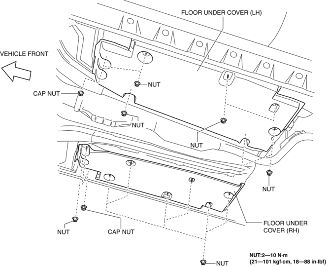
2. Remove the cap nuts.
3. Remove the nus.
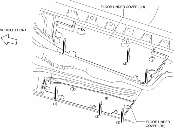
4. Pull the floor under covers in the direction of arrow (1), (2), (3) shown in the figure, and then remove it.
5. Install in the reverse order of removal.
 Extractor Chamber Removal/Installation
1. Disconnect the negative battery cable..
2. Remove the rear combination light..
3. Remove the rear bumper..
4. Remove the clips.
5. Install in the reverse order of removal. ...
 Front Beltline Molding Removal/Installation
1. Fully open the front door glass.
2. Disconnect the negative battery cable..
3. Remove the inner garnish..
4. Remove the front door trim..
5. Remove the power outer mirror..
6. Remove clip ...
Other materials:
Locking Lug Nuts
If your vehicle has Mazda optional
antitheft wheel lug nuts, one on each
wheel will lock the tires and you must
use a special key to unlock them. This
key will attach to the lug wrench.
Register them with the lock manufacturer
by filling out the card provided in the
glove compartment and ma ...
Engine Disassembly/Assembly [Skyactiv G 2.0]
CAUTION:
When the transaxle is installed, do not suspend the engine. Otherwise, the
SST installation area of the cylinder head may be damaged due to excess weight.
Only suspend the engine after separating the engine and transaxle.
Applying excessive force (force of 100 N {10.2 ...
Drive Belt Removal/Installation [Mzr 2.3 Disi Turbo]
1. Remove the aerodynamic under cover No.2 and splash shield as a single unit..
2. Rotate the drive belt auto tensioner in the direction shown in the figure
and remove the drive belt.
3. Install the drive belt.
4. Verify that the drive belt auto tensioner indicator mark does not exceed ...
