Mazda 3 Service Manual: Forced Ignition On [With Advanced Keyless Entry And Push Button Start System]
NOTE:
-
In order to perform a forced ignition ON, the M-MDS (IDS) is necessary. If the servicing is being done outside of an Authorized Mazda dealership, contact an Authorized Mazda dealership for instructions.
-
The forced ignition ON procedure forces a power supply to each part when no power is available even after the ignition switch has been operated. However, the engine cannot be started and the steering cannot be unlocked.
-
When performing a forced ignition ON procedure, remove all advanced keys from the vehicle. If an advanced key is left in the vehicle, the forced ignition ON procedure cannot be done.
1. Verify that there are no advanced keys in the vehicle.
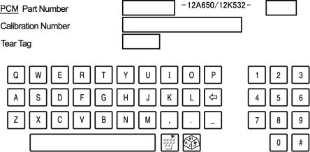
2. Get PCM part number from As-built site.
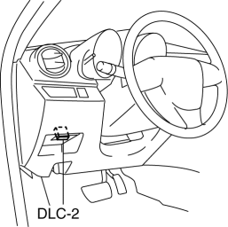
3. Connect the M-MDS (IDS) to the DLC-2.
4. Manual vehicle identification.
-
Select “Manual Vehicle Entry”.
5. Select the “All other” from Vehicle list.
6. Input the PCM part number on the following screen.
7. After the vehicle is identified, select the following items from the initialization screen of the IDS.
-
Select “Body”.
-
Select “Special Ignition ON”.
8. Perform the procedure according to the directions on the screen.
9. Delete session with keeping ignition ON.
10. Normal vehicle identification.

 Relay Block Inspection [With Advanced Keyless Entry And Push Button Start System]
1. Disconnect the negative battery cable..
2. Remove the following parts:
a. Driver-side front scuff plate.
b. Driver-side front side trim.
c. Hood release lever.
d. Upper panel.
e. Shift ...
Other materials:
High Mount Brake Light Disassembly/Assembly
4SD
1. Disconnect the negative battery cable..
2. Remove the trunk lid trim..
3. Remove the high-mount brake light..
4. Remove the high-mount brake light outer lens.
5. Remove the high-mount brake light inner lens.
6. Remove the screws (with advanced keyless entry and push button ...
Rear Seat Back Frame Removal/Installation
1. Remove the rear seat cushion..
2. Remove the rear buckle installation bolt..
3. Remove the rear seat back..
4. Remove the headrest.
5. Open the fasteners.
6. Detach the hooks.
7. Remove the child-restraint seat anchor covers in the order of (1), (2) as
shown in the figure. (5H ...
How to use AUX mode (Type B)
Select the icon on the home screen to display the Entertainment screen.
Select to switch to the AUX mode. The following icons are
displayed in the lower
part of the center display.
Icon
Function
Displays the Entertainment menu. Use to switch to a diffe ...
