Mazda 3 Service Manual: Front Bumper Removal/Installation
1. Disconnect the negative battery cable..
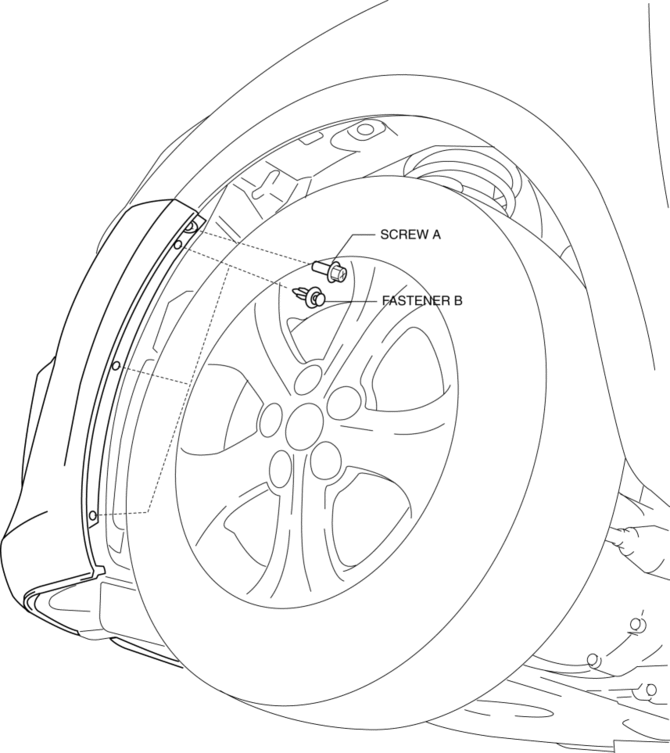
2. Remove the screw A and fasteners B.
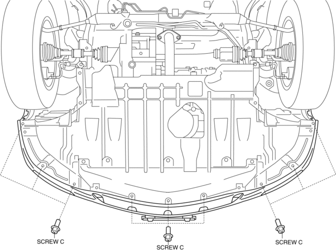
3. Remove the screws C.
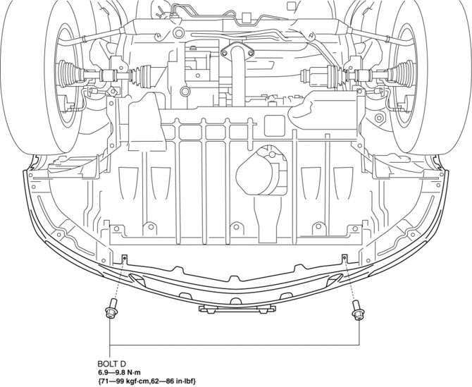
4. Remove the bolts D.
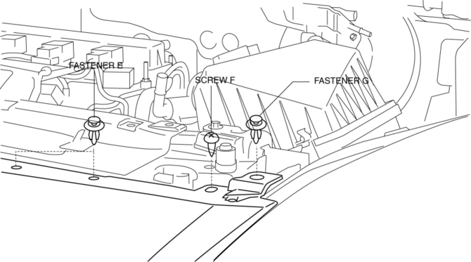
5. Remove the fasteners E, screw F and fastener G.
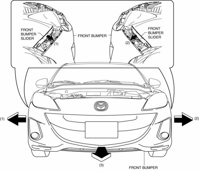
6. Pull the front bumper in the direction of the arrow in the order of (1), (2) and (3), then remove the front bumper..
CAUTION:
-
The front bumper and front bumper slider are engaged firmly. If they are disengaged forcibly the bumper could fall and be damaged. Perform the servicing carefully when disengaging the front bumper from the front bumper slider.
-
When disengaging the front bumper from the front bumper slider, the front bumper could fall and be damaged. Support the front bumper so that it does not fall.
7. Disconnect the front fog light connector. (Vehicles with front fog lights)
8. Install in the reverse order of removal.
9. Adjust the front fog light aiming for vehicles with front fog lights..
Front Bumper Installation Note
1. Spread the front bumper ends apart.
CAUTION:
-
The front bumper and front bumper slider are engaged firmly. If they are disengaged forcibly the bumper could fall and be damaged. Perform the servicing carefully when disengaging the front bumper from the front bumper slider.
-
When disengaging the front bumper from the front bumper slider, the front bumper could fall and be damaged. Support the front bumper so that it does not fall.
2. Attach the front bumper to the body.
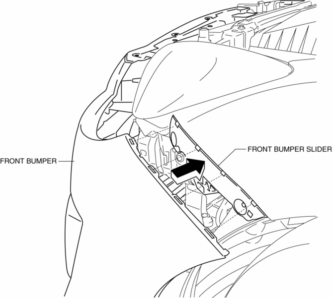
3. Press the front bumper connecting area in the direction of the arrow shown in the figure to engage with the front bumper slider.
Front Bumper of New Parts Installation Note
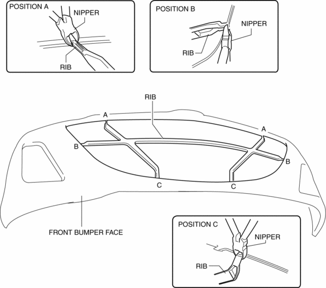
1. Paint the front bumper face.
2. Cut the rib position of A, B, and C from the base with using a nipper.
 Front Bumper Reinforcement Removal/Installation
1. Disconnect the negative battery cable..
2. Remove the following parts:
a. Front bumper.
b. Seal plate.
3. Remove the bolts A.
4. Remove the bolts B.
5. Remove the front bumper r ...
 Front Fender Panel Removal/Installation
1. Disconnect the negative battery cable..
2. Remove the following parts:
a. Front bumper.
b. Front combination light.
c. Front fender molding.
d. Side step molding.
3. Remove fasteners an ...
Other materials:
Antenna Feeder No.2 Inspection
1. Disconnect the negative battery cable..
2. Remove the following parts:
a. A-pillar trim (RH).
b. Rear seat cushion (4SD).
c. Rear scuff plate (RH).
d. Tire house trim (RH).
e. Trunk side upper trim (5HB, RH).
f. Trunk side trim (5HB, RH).
g. C–pillar trim (RH).
3. Disconnect t ...
Back Up Light Bulb Removal/Installation
4SD
1. Disconnect the negative battery cable..
2. Remove the trunk rid trim..
3. Disconnect the connector.
4. Rotate the socket in the direction of the arrow as shown in the figure to
remove it.
5. Remove the back-up light bulb.
6. Install in the reverse order of removal.
...
PKSB (Parking Support Brake)
The Subaru Solterra PKSB (Parking Support Brake) system is engineered
to assist the driver during low-speed maneuvers, such as parking, by issuing warnings
and automatically applying braking force to help reduce potential collision damage
with detected obstacles.
PKSB (Parking Support Brake) ...
