Mazda 3 Service Manual: Headlight Bulb Removal/Installation
Halogen Type
Low-beam
1. Disconnect the negative battery cable..
2. Disconnect the connector.
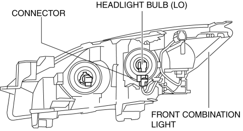
3. Remove the cover.

4. Remove the adaptor.
5. Remove the headlight bulb (LO).
CAUTION:
-
A halogen bulb generates extremely high heat when it is illuminated. If the surface of the bulb is soiled, excessive heat will build up and the life of the bulb will be shortened. When replacing the bulb, hold the metal flange, not the glass.
6. Install in the reverse order of removal.
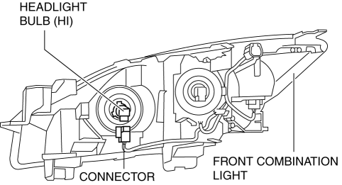
High-beam
1. Disconnect the negative battery cable..
2. Disconnect the connector.
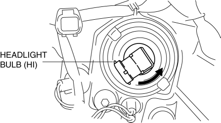
3. Rotate the headlight bulb (HI) in the direction of the arrow shown in the figure to remove it.
4. Remove the headlight bulb (HI).
CAUTION:
-
A halogen bulb generates extremely high heat when it is illuminated. If the surface of the bulb is soiled, excessive heat will build up and the life of the bulb will be shortened. When replacing the bulb, hold the metal flange, not the glass.
5. Install in the reverse order of removal.
Discharge Type
WARNING:
-
Incorrect servicing of the discharge headlight bulb could result in electrical shock. Before servicing the discharge headlight bulb, always refer to the service warnings..
1. Disconnect the negative battery cable..
2. Remove the front bumper..
3. Remove the front combination light..
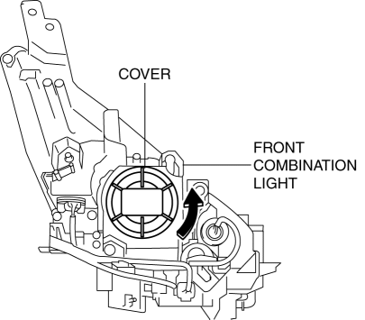
4. Rotate the cover in the direction of the arrow shown in the figure to remove it.
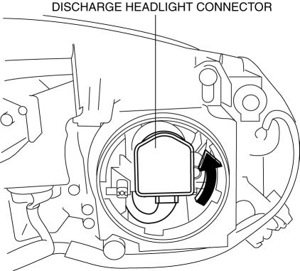
5. Rotate the discharge headlight connector in the direction of the arrow shown in the figure to remove it.
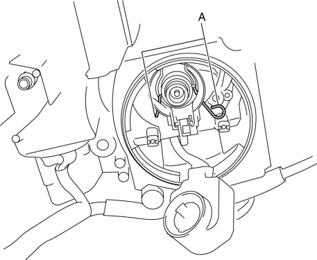
6. Press sections A to release the bulb retaining wire.
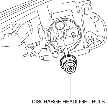
7. Remove the discharge headlight bulb.
CAUTION:
-
The bulb generates extremely high heat when it is illuminated. If the surface of the bulb is soiled, excessive heat will build up and the life of the bulb will be shortened. When replacing the bulb, hold the metal flange, not the glass.
8. Install in the reverse order of removal.
.
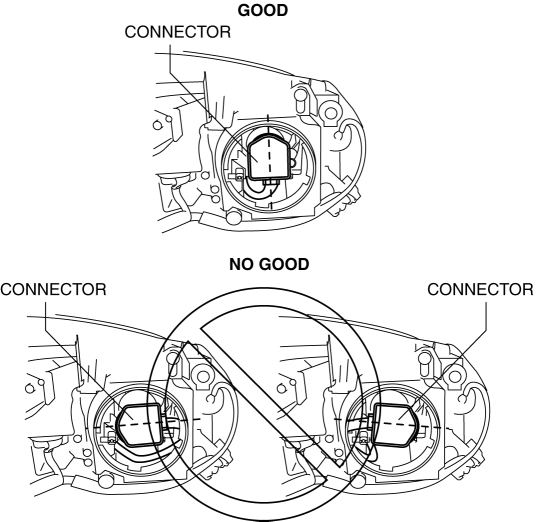
Discharge headlight connector installation note
CAUTION:
-
If the installation direction of the discharge headlight connector is incorrect when the connector is installed, the connector may contact the front combination light housing during the AFS operation and the AFS may not operate normally. After installing the connector to the position shown in the figure, verify that the connector does not contact the front combination light housing.
 Headlight Auto Leveling System Initialization
CAUTION:
If the headlight auto leveling initial setting is not stored correctly, the
headlight auto leveling system may not operate normally. To store the initial
setting correctly, perf ...
 Headlight Leveling Actuator Inspection
NOTE:
Headlight leveling actuator are integrated with the front combination light.
For the actuator inspection of the headlight auto leveling system, perform
the headlight leveling ...
Other materials:
Seat Warmer
The front seats are electrically heated. The
ignition must be switched ON.
Press the seat warmer switch to illuminate
the indicator light while the ignition
is switched ON. The mode changes as
follows each time the seat warmer switch
is pressed.
WARNING
Be careful when using t ...
Solenoid Valve Removal/Installation [FS5 A EL]
WARNING:
A hot transaxle and ATF can cause severe burns. Turn off the engine and wait
until they are cool.
Primary Control Valve Body
1. Remove the primary control valve body.
a. Remove the battery cover..
b. Disconnect the negative battery cable.
c. Remove the aerodynamic un ...
Slide Motor Inspection
1. Remove the battery cover..
2. Disconnect the negative battery cable and wait 1 min or more..
3. Disconnect the slide motor connector.
4. Apply battery positive voltage to the slide motor terminals and inspect the
slide motor operation
If not as specified, replace the front sea ...
