Mazda 3 Service Manual: Headlight Leveling Switch Removal/Installation
1. Disconnect the negative battery cable..
2. Remove the switch panel in the direction of the arrow shown in the figure.
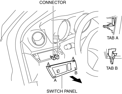
3. Disconnect the connector.
4. Remove the headlight leveling switch in the direction of the arrow (2) shown in the figure while pressing the tabs in the direction of the arrow (1).
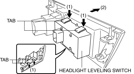
5. Remove the headlight leveling switch.
6. Install in the reverse order of removal.
 Headlight Leveling Switch Inspection
1. Disconnect the negative battery cable..
2. Remove the headlight leveling switch..
3. Verify that the resistance and continuity between the headlight leveling switch
terminals is as indicated ...
 No.6 Bsm Indicator Light Flashes While Not Under Bsm Indicator Light Flashing
Conditions (No Combination Switch Operation (Turn Signal Switch)) [Blind Spot Monitoring
(Bsm)]
No.6 Bsm Indicator Light Flashes While Not Under Bsm Indicator Light Flashing
Conditions (No Combination Switch Operation (Turn Signal Switch)) [Blind Spot Monitoring
(Bsm)]
6
BSM indicator light flashes while not under BSM indicator light-flashing
conditions (no combination switch operation (turn signal switch)
Description
...
Other materials:
Volume/Display/Sound Controls
Volume adjustment
Turn the commander switch volume dial.
The volume switch on the steering switch
can also be pressed.
Display setting
Select the icon on the home
screen to
display the Settings screen.
Select the tab to select the item
you
would like to change.
Display OFF/Cloc ...
Front Passenger Occupant Classification System
First, please read "Supplemental Restraint System (SRS) Precautions"
carefully.
Front Passenger Seat Weight Sensor
Your vehicle is equipped with a front passenger seat weight sensors as a part
of the
supplemental restraint system. These sensors are located under both of the front
p ...
Overloading
WARNING
Be careful not to overload your vehicle:
The gross axle weight rating (GAWR)
and the gross vehicle weight rating
(GVWR) of the vehicle are on the
Motor Vehicle Safety Standard Label
on the driver's door frame. Exceeding
these ratings can cause an accident
or ve ...
