Mazda 3 Service Manual: Oil Control Valve (OCV) Inspection [Mzr 2.0, Mzr 2.5]
Coil Resistance Inspection
1. Remove the battery cover..
2. Disconnect the negative battery cable..
3. Remove the plug hole plate..
4. Disconnect the OCV connector.
5. Measure the resistance between terminals A and B using an ohmmeter.
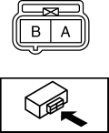
-
OCV coil resistance
-
6.9—7.9 ohms [20°C {68°F}]
-
If not as specified, replace the OCV..
6. Install in the reverse order of removal.
Spool Valve Operation Inspection
1. Remove the OCV..
2. Verify that the spool valve in the OCV is in the maximum valve timing retard position as indicated in the figure.
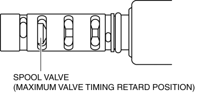
-
If not as specified, replace the OCV..
3. Verify that the battery is fully charged..
-
If not as specified, recharge the battery..
NOTE:
-
When applying battery positive voltage between the OCV terminals, the connection can be either of the following:
-
Positive battery cable to terminal A, negative battery cable to terminal B
-
Positive battery cable to terminal B, negative battery cable to terminal A
4. Apply battery positive voltage between the OCV terminals and verify that the spool valve operates and moves to the maximum valve timing advance position.
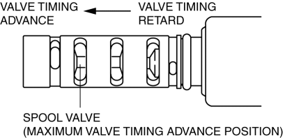
-
If not as specified, replace the OCV..
5. Stop applying battery positive voltage and verify that the spool valve returns to the maximum valve timing retard position.
-
If not as specified, replace the OCV..
6. Install the OCV..
 Electro Hydraulic Power Assist Steering (EHPAS) Control Module Inspection
Terminal Voltage Table (Reference)
Terminal
Signal name
Connected to
Measured item
Measured terminal (measured condition)
...
 Oil Control Valve (OCV) Inspection [Mzr 2.3 Disi Turbo]
Coil Resistance Inspection
1. Remove the battery cover..
2. Disconnect the negative battery cable..
3. Disconnect the OCV connector.
4. Measure the coil resistance between terminals A and B usi ...
Other materials:
Antilock Brake System (ABS)
The ABS control unit continuously
monitors the speed of each wheel. If
one wheel is about to lock up, the ABS
responds by automatically releasing and
reapplying that wheel's brake.
The driver will feel a slight vibration in
the brake pedal and may hear a chattering
noise from the brake syst ...
General Procedures (Steering)
Wheel and Tire Installation
1. When installing the wheels and tires, tighten the wheel nuts in a criss-cross
pattern to the following tightening torque.
Tightening torque
88—118 N·m {9.0—12 kgf·m, 65—87 ft·lbf}
Connector Disconnection
1. Disconnect the negative batte ...
Seat belts
Before driving your Subaru Solterra, always confirm that every occupant
is properly secured with a seat belt. Correct usage of seat belts is one of the
most critical safety measures in preventing serious injuries.
WARNING
Carefully follow the precautions below to minimize the risk of injury du ...
