
Mazda 3 Service Manual: Precaution [Dynamic Stability Control (DSC)]
1. The ABS warning light and/or brake system warning light and/or DSC indicator light and/or DSC OFF light illuminate even when the system is normal.
|
Warning lights that may illuminate and/or flash |
Cases in which the light may illuminate |
Conditions in which the light will go out |
ABS, EBD, TCS and DSC control |
|
Only the front wheels rotate under the following condition while jacked up, stuck or on the chassis dynamometer:
|
After turning off the ignition once and then restarting the engine, the vehicle is driven at 10km/h {6.2 mph} or more , and then normal operation is verified. |
|
|
Parking brake is not fully released while driving. |
|||
|
Brake drag. |
|||
|
Sudden acceleration/deceleration. |
|||
|
Left/right or front/rear tires are different. (Size, radius, tire pressure or wear is other than that listed on tire label.) |
|||
|
Battery voltage at DSC HU/CM ignition terminal Y drops below about 9.5 V *2. |
Battery voltage rises above about 9.5 V . |
|
|
|
Brake fluid amount is low. |
Brake fluid level lower than recommended amount. |
|
|
Brake switch signal error (stuck at on/off) |
Normal operation of brake switch signal is verified |
|
*1 In case where the light may illuminate, only when DSC HU/CM detects that a wheel-speed sensor determines that more than two wheels are malfunctioning.
*2 If battery voltage drops below 10 V
while vehicle speed is greater than 3 km/h {2 mph}
, DSC HU/CM detects DTC U3003:16.
2. Precautions during servicing of DSC. The DSC is composed of electrical and mechanical parts. It is necessary to categorize malfunctions as being either electrical or hydraulic when performing troubleshooting.
a. Malfunction in electrical system
-
The control module has an on-board diagnostic function. With this function, the ABS warning light and/or brake system warning light and/or DSC indicator light and/or DSC OFF light will come on when there is a problem in the electrical system.
Also, past and present malfunctions are recorded in the control module. This function can find malfunction that do not occur during periodic inspections. Connect the M-MDS to the DLC-2. The stored malfunctions will be displayed in the order of occurrence. To fine out the causes of DSC malfunction, use these on-board diagnostic results.
-
If a malfunction occurred in the past but is now normal, the cause is likely a temporary poor connection of the harness.
The control module usually operates normally. Be careful when searching for the cause of malfunction.
-
After repair, it is necessary to clear the DTC from the control module memory.
Also, if the DSC related parts have been replaced, verify that no DTC has been displayed after repairs.
-
After repairing the ABS wheel-speed sensor or ABS sensor rotor, or after replacing the control module, the ABS warning light may not go off even when the ignition is switched ON. In this case, drive the vehicle at a speed of 10 km/h {6.2 mph} or more
, make sure the ABS warning light goes off, then clear the DTC.
-
When repairing, if the DSC related connectors are disconnected and the ignition is switched ON, the control module will mistakenly detect a fault and record it as a malfunction.
CAUTION:
-
In DSC vehicles, when any DSC HU/CM, steering angle sensor and SAS control module are replaced, perform the sensor standard point installation of each sensor.
-
-
To protect the control module, make sure the ignition is off before connecting or disconnecting the control module connector.
b. Malfunctions in hydraulic system
-
Symptoms in a hydraulic system malfunction are similar to those in a conventional brake malfunction. However, it is necessary to determine if the malfunction is in a DSC component or the conventional brake system.
-
The hydraulic unit contains delicate mechanical parts. If foreign materials get into the component, the DSC may fail to operate. Also, it will likely become extremely difficult to find the location of the malfunction in the event that the brakes operate but the DSC does not. Make sure foreign materials do not get inside when servicing the DSC (e.g.brake fluid replacement, pipe removal).
Intermittent Concern Troubleshooting
Vibration method
-
If malfunction occurs or becomes worse while driving on a rough road or when engine is vibrating, perform the steps below.
NOTE:
-
There are several reasons why vehicle or engine vibration could cause an electrical malfunction. Some of the things to check for are:
-
Connectors not fully seated.
-
Wire harnesses not having full play.
-
Wires laying across brackets or moving parts.
-
Wires routed too close to hot parts.
-
An improperly routed, improperly clamped, or loose harness can cause wiring to become pinched between parts.
-
The connector joints, points of vibration, and places where wire harnesses pass through the firewall, body panels, etc. are the major areas to be checked.
Inspection method for switch connectors or wires
1. Connect the M-MDS to DLC-2.
2. Switch the ignition to ON (engine off).
NOTE:
-
If engine starts and runs, perform the following steps at idle.
3. Access the PIDs for the switch you are inspecting.
4. Turn switch on manually.
5. Shake each connector or wire harness a bit vertically and horizontally while monitoring the PID.
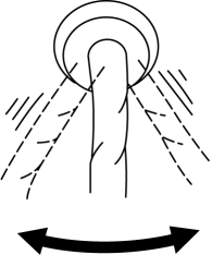
-
If the PID value is unstable, check for poor connection.
Inspection method for sensor connectors or wires
1. Connect the M-MDS to DLC-2.
2. Switch the ignition to ON (engine off).
NOTE:
-
If engine starts and runs, perform the following steps at idle.
3. Access the PIDs for the switch you are inspecting.
4. Shake each connector or wire harness a bit vertically and horizontally while monitoring the PID.
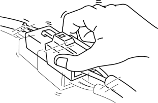
-
If the PID value is unstable, check for poor connection.
Inspection method for sensors
1. Connect the M-MDS to DLC-2.
2. Switch the ignition to ON (engine off).
NOTE:
-
If engine starts and runs, perform the following steps at idle.
3. Access the PIDs for the switch you are inspecting.
4. Vibrate the sensor slightly with your finger.
-
If the PID value is unstable or malfunction occurs, check for poor connection and/or poorly mounted sensor.
Malfunction data monitor method
1. Perform malfunction reappearance test according to malfunction reappearance mode and malfunction data monitor. The malfunction cause is found in the malfunction data.
Connector terminal check method
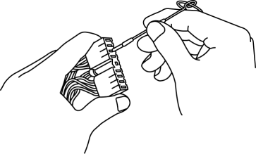
1. Check the connection condition of each female terminal.
2. Insert a male terminal to the female terminal and inspect the female terminal for looseness.
 DSC Sensor Initialization Procedure
WARNING:
If the DSC sensor initialization procedure is not completed, the DSC will
not operate properly and it might cause an unexpected accident. Therefore, after
replacing or removing ...
 ABS
ABS
...
Other materials:
Air Intake Actuator Removal/Installation [Manual Air Conditioner]
1. Set the air intake mode to FRESH.
2. Disconnect the negative battery cable..
3. Remove the following parts:
a. Front scuff plate (Passenger-side).
b. Front side trim (Passenger-side).
c. Dashboard under cover.
d. Glove compartment.
e. Lower panel (Passenger-side).
f. Shower duct ( ...
Direct Mode
Direct mode can be used for temporarily
switching gears by operating the steering
shift switch while the vehicle is being
driven with the selector lever in the D
range.
While in direct mode, the D and M
indication illuminate and the gear position
in use is illuminated.
Direct mode is can ...
Power Outer Mirror Inspection
Mirror Glass Adjustment Motor
1. Disconnect the negative battery cable..
2. Remove the inner garnish..
3. Disconnect the power outer mirror connector.
4. Remove the front door trim..
5. Apply battery positive voltage and connect the ground to the power outer mirror
terminals and inspect t ...
