Mazda 3 Owners Manual: Removing a Flat Tire
- If your vehicle is equipped with a wheel cover, pry off the wheel cover with the beveled end of the jack lever.
NOTE Force the end of the jack lever firmly between wheel and cover, or removal will be difficult.
| CAUTION
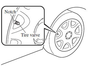
Align the notch on the wheel cover
with the valve stem when installing it.
Damage could occur during installation if the wheel cover is not properly aligned. |
- Loosen the lug nuts by turning them counterclockwise one turn each, but do not remove any lug nuts until the tire has been raised off the ground
- Place the jack on the ground.
- Turn the jack screw in the direction shown in the figure and adjust the jack head so that it is close to the jack-up position
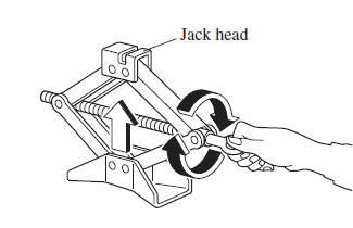
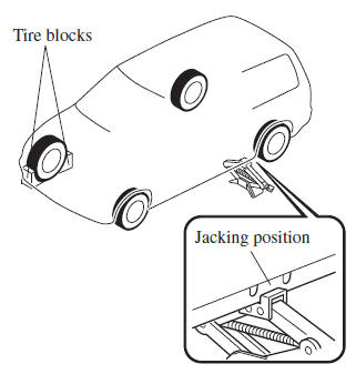
- Place the jack under the jack-up position closest to the tire being changed with the jack head squarely under the jack-up point.
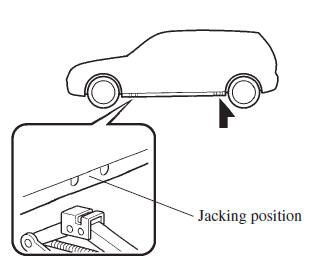
- Continue raising the jack head gradually by rotating the screw with your hand until the jack head is inserted into the jack-up position.
| WARNING
Use only the front and rear jacking
positions recommended in this manual:
Attempting to jack the vehicle
in positions other than those
recommended in this manual is
dangerous. The vehicle could slip off
the jack and seriously injure or even kill
someone. Use only the front and rear
jacking positions recommended in this
manual Do not jack up the vehicle in a position other than the designated jack-up position or place any objects on or under the jack: Jacking up the vehicle in a position other than the designated jack-up position or placing objects on or under the jack is dangerous as it could deform the vehicle body or the vehicle could fall off the jack resulting in an accident. Use only the jack provided with your Mazda: Using a jack that is not designed for your Mazda is dangerous. The vehicle could slip off the jack and seriously injure someone. Never place objects under the jack: Jacking the vehicle with an object under the jack is dangerous. The jack could slip and someone could be seriously injured by the jack or the falling vehicle. |
- Insert the jack lever and attach the lug wrench to tire jack.
- Turn the jack handle clockwise and raise the vehicle high enough so that the spare tire can be installed. Before removing the lug nuts, make sure your Mazda is firmly in position and that it cannot slip or move.
| WARNING
Do not jack up the vehicle higher than is
necessary:
Jacking up the vehicle higher than
is necessary is dangerous as it could
destabilize the vehicle resulting in an
accident.
Do not start the engine or shake the vehicle while it is jacked up: Starting the engine or shaking the vehicle while it is jacked up is dangerous as it could cause the vehicle to fall off the jack resulting in an accident. Never go under the vehicle while it is jacked up: Going under the vehicle while it is jacked up is dangerous as it could result in death or serious injury if the vehicle were to fall off the jack. |
- Remove the lug nuts by turning them counterclockwise; then remove the wheel and center cap.
 Changing a Flat Tire
NOTE
If the following occurs while driving, it
could indicate a flat tire.
Steering becomes difficult.
The vehicle begins to vibrate
excessively.
The vehicle pulls in one direction.
If ...
 Locking Lug Nuts
If your vehicle has Mazda optional
antitheft wheel lug nuts, one on each
wheel will lock the tires and you must
use a special key to unlock them. This
key will attach to the lug wrench.
Registe ...
Other materials:
Fuel Gauge
The fuel gauge shows approximately
how much fuel is remaining in the tank
when the ignition is switched ON. We
recommend keeping the tank over 1/4 full.
Type A/Type B instrument cluster
Type C instrument cluster
If the low fuel warning light illuminates or
the fuel level is very low, ...
Airflow Mode Main Link Removal/Installation
1. Set the air intake mode to FRESH.
2. Set the air mix mode to MAX COLD.
3. Disconnect the negative battery cable..
4. Remove the following parts:
a. Front doors.
b. Front scuff plate.
c. Front side trim.
d. Dashboard under cover.
e. Glove compartment.
f. Upper panel.
g. Shift l ...
Electro Hydraulic Power Assist Steering (EHPAS) Control Module Configuration
CAUTION:
If the EHPAS CM configuration is not completed, the EHPAS will not operate
properly. If the EHPAS CM is replaced, always carry out the EHPAS CM configuration
so that the EHPAS operates properly.
1. Connect the M-MDS (IDS) to the DLC-2.
2. After the vehicle is ident ...
